Thanks Nelson... I am a real geek with ultra simplistic circuits
This morning before going to the office.. I switched the 2Sk170 for 2N3819s ..and measured the THD adn Voptimum.. I tried a few.. .. I did make a small change to the circuit so were njot able to make full comparisons..
This morning before going to the office.. I switched the 2Sk170 for 2N3819s ..and measured the THD adn Voptimum.. I tried a few.. .. I did make a small change to the circuit so were njot able to make full comparisons..
Attachments
It seems that the 2N3819 might be a cheap alternative to teh 2SK170....
Results for 4 samples of 2N3819 1 Vrms out at 1KHz:
sample 1]
0.18% THD, pure H3, Vopt = 21 Volt, gain=18dB
sample 2]
0.15% THD, pure H3, Vopt = 23.3Volt, gain = 18dB
at 300mVrms THD was 0.02%
sample 3]
0.127% THD, pure H3, Vopt = 26.6Volt, gain 18dB
at 300mVrms THD was 0.015%
sample 4]
0.120% THD , Vopt = 24.5Volt, gain was 19dB
Using sample 4 in the shunt feedback schematic I got these results:
gain = 3.1dB
Vopt = 24.1 Volt
THD at 1 Vrms out was 0.039%
chrzz,
Thijs
I haven't done any listening tests.. but it seems that the 2N3819 follows the same square-root transductance law as the 2Sk170..
Besides that lower gain (18dB v. 26dB), you can expect more noise.. but nothing to worry about... I would say the 2N3819 (selected for Idss => 8mA) would make an excelent low-cost alternative.
grt, T
Besides that lower gain (18dB v. 26dB), you can expect more noise.. but nothing to worry about... I would say the 2N3819 (selected for Idss => 8mA) would make an excelent low-cost alternative.
grt, T
0.48 € vs. 0.10 € aren't that issue in choosing a transistor for a preamp (for me)! You just need 2 pieces for a stereo device. But I don't know how hard it is to match them.
Offcourse, then you're right....
Can you get 2sk170 jfets for 0.48€? I would love to buy some more for that price...
Can you get 2sk170 jfets for 0.48€? I would love to buy some more for that price...
Thanks, tschrama, for this ideas and tests, because this FET is easy available and cheap enough for a precise matching and selection.
Sorry to ask a stupid question, but did you select the 2N3819 for the right IDSS before this very interesting test? And how?
I posted before the relative similarity of the JFET BOZ and the TNTAudio Preamble. I also found several other audio circuits in old ELRAD mags using the 2N3819 (in 12V circuits, mostly with another transistor for low impedance output or CCS).
I wonder why this JFET - although widely used "elsewhere" - is so underrated here: Is it only because of noise? That should not be a big problem in a line level circuit. But I do not have an THD analyzer to optimize these circuits.
Hi lohk,
No, i didn't select the 2N3819 jfets at all.
After the tests I measured the Idss of the last two JFET (sample 3] and 4]. The Idss of two fo them were:7.39mA and 8.53mA, optimum Voltage supply was about 25 and 27 Volts.
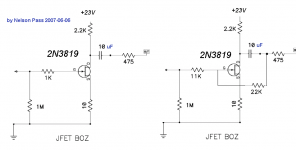
Yesterday I measured them again in the exact same circuits as I used for the 2SK170 (the original Nelson Pass JFET BOZ), so with two 2K2 resistors:
They had the same THD as the 2SK170 with Idss = 8mA, but need a higher voltage supply (22.3Volts for the 2N3819, 16.3Volts for the 2Sk170).
I don't understand why the 2N3819 isn't regarded as a fine alternative for the 2Sk170 in line applications.
Although internal resistance is a bit higher, transductance is a bit lower, noise is a bit higher... the 2N3819 works absolutely fine in this application.
Goodluck,
Thijs
No, i didn't select the 2N3819 jfets at all.
After the tests I measured the Idss of the last two JFET (sample 3] and 4]. The Idss of two fo them were:7.39mA and 8.53mA, optimum Voltage supply was about 25 and 27 Volts.
Yesterday I measured them again in the exact same circuits as I used for the 2SK170 (the original Nelson Pass JFET BOZ), so with two 2K2 resistors:
They had the same THD as the 2SK170 with Idss = 8mA, but need a higher voltage supply (22.3Volts for the 2N3819, 16.3Volts for the 2Sk170).
I don't understand why the 2N3819 isn't regarded as a fine alternative for the 2Sk170 in line applications.
Although internal resistance is a bit higher, transductance is a bit lower, noise is a bit higher... the 2N3819 works absolutely fine in this application.
Goodluck,
Thijs
The 2N3820 would be the equivalent P-version.
But that is only theoretical, I do not know how good they are compatible in practice.
But that is only theoretical, I do not know how good they are compatible in practice.
Thanks, Thijs, for that series of tests. I will try to make a 2N3819 version as soon as time (and outside temperature) permits.
Did you do some critical listening yet?
all the best
Did you do some critical listening yet?
all the best
lohk said:The 2N3820 would be the equivalent P-version.
But that is only theoretical, I do not know how good they are compatible in practice.
Much higher capacitances in the 3820, but otherwise they seem fairly complementary, judging from the rudimentary datasheets I have found.
No listening tests yet... but I should defenitely do that ... the distortion character will change dramaticly when you adjust the power supply for low THD.. from allmost 100% second harmonic, to allmost 100% third harmonic....
PS
I also wondered about a 2N3819 complementary... so a bought a few and just received 50 2n3820 JFETs in my mail box today... 0.10$/piece
PS
I also wondered about a 2N3819 complementary... so a bought a few and just received 50 2n3820 JFETs in my mail box today... 0.10$/piece
So ... because this Optimum Voltage, 2nd harmonic canceling, thingy that Nelson suggests works so marvelously... I got thinking...:
I have just completed a Pacific RIAA pre (with the MC pre) amplifier last month or so, and judging from my measurements, the suggested supply voltages are WAY to high.. so I hooked it up to my HP 339A (my pride and joy).. here goes:
Power supply +24Volt, as the circuit suggests:
1mV input, 400mV output, THD = 0.3% , purely 2nd harmonic
now with optimum power Supply + 13.7Volt
1mV input, 340mV output, THD = 0.0485% , purely 3rd harmonic
Yep... 😎
tschrama said:So ... because this Optimum Voltage, 2nd harmonic canceling, thingy that Nelson suggests works so marvelously...
Can you draw me a picture? I'd like to see how you graph this out in order to cement, or jack-hammer, my ideas on how this is done.
I've been using the ID/VDS graph and adjusting my amp's values until the transistor's voltage/current falls on one of the graph's curves. Is this correct?
Many thanks,🙂
Think about it as presented in ZV9. Working the load line is
something that the smarter tube guys have done for a long time.
😎
something that the smarter tube guys have done for a long time.
😎
Nelson Pass said:Think about it as presented in ZV9. Working the load line is
something that the smarter tube guys have done for a long time.
😎
It's a great feeling when a newbie, like me, can learn something important.
Thanks Nelson,--this is so cool! When simming out a schematic that employs the LU1014D jfet, I've been staying on the lowest VGS curve and adjusting my voltage/amperage to match that curve.
That's what got me to wondering about the mosfets--could it be the same?
It's weird how much amperage some of the mosfets must have to stay on a VGS curve--I'm thinking IRFP044N as an example. When tracking the lowest (4.5V) curve, I have to have about 6 amps for anything over 10 volts. That's a lot of amps to add to the bias.
The big, bad situation I can't always resolve occurs when the bias wattage is around 100 watts per device! To keep the IRFP044N linear, I have to run high amperage, but low voltage... or switch to a mosfet that's more suitable.
Still, I have a bunch of these guys, so I'd better learn how to do this.🙂
carpenter said:That's what got me to wondering about the mosfets--could it be the same?
Not exactly, but I do have some very interesting stuff happening
there.
Nelson Pass said:
Not exactly, but I do have some very interesting stuff happening
there.
Hmmmm, I was wondering about that too this mornig... I have an original Bridge Of Zen, and I can manipulate the Voltage supply with my variac...Would like to see what happens t'night....🙄
- Home
- Amplifiers
- Pass Labs
- Jfet BOZ