Hi All,
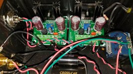
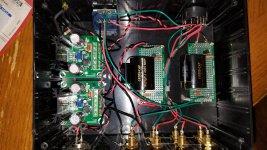
I purchased a jfet boz from another forum member (he is not the original builder). I would like to know how to set the bias on this (please be as detailed as possible I'm not overly technical but have no problem opening up and using my multimeter). All I know about it is that it has a 19v smps regulated down to 16v , 20k alps blue velvet pot, and what can be seen in photos. I will be using the pre between my bluesound node 2 and an F6 clone. Thanks for your input.
Tony
Attachments
can't see any JFet on these pcbs
have schm ?
care to shot pcbs above , and tell what's T0220 part behind these heatsinks ?
any other electronics in that case ?
have schm ?
care to shot pcbs above , and tell what's T0220 part behind these heatsinks ?
any other electronics in that case ?
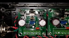


The boards labeled “audiowind” are lm317 regulators. The Jfet BoZ is on the 3x7 perfboard. I don’t know why you want to check the bias but it’s not adjustable other than changing resistors. There is only a single jfet to bias, so it’s not like you can crank it up...it’s either good or it’s not. And without taking those boards out it’s hard to tell what resistor is doing what.
Does it sound distorted?
Does it sound distorted?
I Have not tried it yet in my system only plugged it in and front led lit up and 1 green led board lit second boards led did not come on. That is all I have done so far.
LED might be broken. It’s not part of the circuit, just an indicator.
I’d test for dc on output rca but you should be fine. It’s cap coupled. I’d do this before plugging it into a power amp.
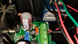
You can make sure the regulator is working by testing the black and red leads going to the Jfet BoZ boards. Should be + 18vdc or so.
I’d test for dc on output rca but you should be fine. It’s cap coupled. I’d do this before plugging it into a power amp.
You can make sure the regulator is working by testing the black and red leads going to the Jfet BoZ boards. Should be + 18vdc or so.
Ok I will do those tests tomorrow and post the readings, again thanks for your time and all information on what to test for.
Thanks Tony
Thanks Tony
I originally built it. You should listen to it before making any changes.
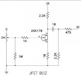
Second post has the schematic in the link below. The 10 Ohm resistor was changed to 22 ohm.
The regs are LM317 based. I don't know what's wrong with the LED. Its was fine 2 years ago when it was built.
If you think you want to replace the reg, it's only $6 to $10 from Parts Express.
Jfet BOZ
Vince
Second post has the schematic in the link below. The 10 Ohm resistor was changed to 22 ohm.
The regs are LM317 based. I don't know what's wrong with the LED. Its was fine 2 years ago when it was built.
If you think you want to replace the reg, it's only $6 to $10 from Parts Express.
Jfet BOZ
Vince
Last edited:
This is the original schematic. I know I changed the 10 ohm resistor, but don't remember what else, if anything. I just went with what Nelson said to do- 16v, 22 ohm, 8-10 idss jfets. That's it.
I still have the original boz-j I built, and yours sounds better. Can't say why. My original has a discrete volume pot, but this one has slightly "better" caps.
I thought about buying it back when I saw it for sale. 🙂
I built this boz-j to integrate with an ACA. Never happened.
Since I had the parts, I finished it, sold it and donated the funds from the parts cost to charity. That's the back story.
Vince
Attachments
UPDATE
An Update I did some tests there was a loose (ground or negative) going to second board, I redid the connection now LED is lit and boards have 24 DC going in and 16V DC going out to jfet boards. I did not get any dc on output rca's. I will update again after I try it out in my system. Thanks All for the help and suggestions.
An Update I did some tests there was a loose (ground or negative) going to second board, I redid the connection now LED is lit and boards have 24 DC going in and 16V DC going out to jfet boards. I did not get any dc on output rca's. I will update again after I try it out in my system. Thanks All for the help and suggestions.
- Status
- Not open for further replies.
- Home
- Amplifiers
- Pass Labs
- Jfet BoZ bias ?