Zen Mod said:
what about xmass tree?
I mean-out of any amp?
Xmas tree? Or a mid-fi amp, with many glowing red LEDs, just below a tree? When you look at such an amp, don’t you think “they’d better put them inside”.
John Cleese: "what's wrong with ol' plain kiss?"
..Yes sir. Sorry sir. 😀
WARNING! I just started using LTSpice. I have only a particial clue as to what I'm doing with with this very powerful tool. Hey I'm here to learn. What a great hobby.
I hope I attached the right signal sources to the inputs.
-David
I hope I attached the right signal sources to the inputs.
-David
dw8083 said:WARNING! I just started using LTSpice. I have only a particial clue as to what I'm doing with with this very powerful tool. Hey I'm here to learn. What a great hobby.
I hope I attached the right signal sources to the inputs.
-David
I'm dumb for proggies like that;
OK-I'm more lazy........used to ruler and calculator
keep it simple,but not simpler than needed.
you forgot input caps...........
anyway-this circ is more than simple enough ,so you can build it and try without sims;
better put some energy in constructing good enough shunt reg.
and-stay with bipolar supply (+/-) ,just because then you can omit input caps.
all in all-we already have starting schematic-now you can try to implement folowers
Hi,
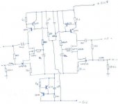
While looking at the schematic that Choky provided in post #78, I was thinking how to modify this circuit to suit the parts that I have in my drawer. And this is the result. The circuit is almost identical to Choky's, I just cascoded a Jfet. While this may seem unnecesary, the reasons were:
I already have a salvaged amp that has a working PSU, giving around +-50 V, so I wanted to use it. I have more Bipolars than mosfets in my drawer, that's why I prefer Choky's CCS. I have LU1014D, so while that my not be the preffered part for a preamp, it should give satisfactory performance in the cascode, as in ZV9.
I do need your help in determining the correct values for R1, R2 and R3 and I was not sure about the value of the Zener diodes, I guess they should be around 6.2 V?
Thank you very much,
Vix
Attachments
Vix said:Hi,
While looking at the schematic ........................
Vix
tonight.............
in a meantime this can be handy
Attachments
dw8083 said:Here's a possible circuit based on Nelson's chewy hints from the top of the thread.
Opinions?
Why not use LSK389s instead of separate 170s that would have to be matched?
se
Steve Eddy said:
Why not use LSK389s instead of separate 170s that would have to be matched?
se
dual or separates........that really depends only of what you are able to have/find
in fact-also p fets vs. n fets.........just rotate everything (flip vertically) and other type can be used
ZM
Babo--sorry, I didn't mean to complain, you guys are aces in my book!
Vix
This is a very interesting thought, I had read in EB's article that the source resistor increased local feedback, but I didn't really understand the mechanism and I never considered using this circuit at very low gain might bring with it the negative attributes of mucho negative feedback......with more source degeneration - local feedback is greater,so also distortion is decreased ; where is sweet spot ? that's really matter of compromise -what you need -greater OLG or lesser already small distortion....ratio between OLG and CLG or local feedback and overall feedback......for my ears -too much of both aren't good
Babo--sorry, I didn't mean to complain, you guys are aces in my book!
Vix
The best method I found is to substitute a small pot in place of that zener. Then tweak it until input sine waves are not flat on top or bottom, but not too peaky either. Usually it is only one or two volts more and the circuit starts oscillating.and I was not sure about the value of the Zener diodes, I guess they should be around 6.2 V?
Steve Eddy said:
Why not use LSK389s instead of separate 170s that would have to be matched?
se
I'm actually going to use LKS389's, I just have not taken the time to build the part in my schematic capture program, so I used LSK170's instead.
BTW, I'm very impressed with SWCad III (LT Spice) from Linear.
http://www.linear.com/designtools/softwareRegistration.jsp
I'm happy to share my schematic with anyone who would like to use SwitcherCad to modify the circuit. The sowftare is free.
-David
Vix said:Hi,
While looking at the schematic that Choky provided in post #78, I was thinking how to modify this circuit to suit the parts that I have in my drawer. And this is the result. The circuit is almost identical to Choky's, I just cascoded a Jfet. While this may seem unnecesary, the reasons were:
I already have a salvaged amp that has a working PSU, giving around +-50 V, so I wanted to use it. I have more Bipolars than mosfets in my drawer, that's why I prefer Choky's CCS. I have LU1014D, so while that my not be the preffered part for a preamp, it should give satisfactory performance in the cascode, as in ZV9.
I do need your help in determining the correct values for R1, R2 and R3 and I was not sure about the value of the Zener diodes, I guess they should be around 6.2 V?
Thank you very much,
Vix
vix
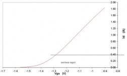
looking at pdf I attached (sorry- I forgot who is here responsible for measuring and drawing that.........Respect!!),seems that LU is good for nothing bellow 300mA........that's 300mA per side,600mA through lower CCS ............meaning that R3=Ube/I = 0V6/0,6 =1E.......plenty for veeeny BD140
even with 300mA (where R1 and R2 are 2E) BD140 will be fried........
you can stay with tiny Jfets for this
.........
but-saythat you can live with some (!!?) NONLINEARITY........CAPSLOCK,then you can try with 100mA per side....R1 3E,R2 and R3 6E.........
use bc556C ,use bd140-16.....and zenners..........(0,1Ax33 +1V4 + 4V) = 8V7..............what is nearest standard value?
anyway-try.........but check dissipations for those bds and trim PS voltages accordingly
to vix again.........with these currents-time for reworking entire schematic......other (more robust) CCS........
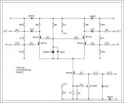
anyway-just as illustration-my variant of famous (hehe) xccsblswhatever preamp for my friend Igor.........singing nice tunes along with Haf9505 on Fried Coffins etc.
in your boots-I'll make something leaned on this schematic......LUs,also CCS-ed above,300mA per side,minimum needed PS voltages
anyway-just as illustration-my variant of famous (hehe) xccsblswhatever preamp for my friend Igor.........singing nice tunes along with Haf9505 on Fried Coffins etc.
in your boots-I'll make something leaned on this schematic......LUs,also CCS-ed above,300mA per side,minimum needed PS voltages
Attachments
Zen Mod said:in your boots-I'll make something leaned on this schematic......LUs,also CCS-ed above,300mA per side,minimum needed PS voltages
Thanks!!
In that case it would start looking more like micro-X-ZV9 with dual rails. 🙂 😎
If I got it right, there will have to be around 600 mA from the lower CCS. (So there would be 1 ohm sensing resistor to set a current of 660 mA)
If the upper CCS-es are used (like those in Aleph P 1.7) instead of 680 R resistors, how much current shall flow through each of them?
The last schematic looks interesting. It strikes me that it doesn't use source resistors, so you have direct X. I don't want to go OT, but it would be nice to know how it compared against plain BOSOZ, or CCS-X-BOSOZ, (with no cascode and source resistors). Maybe that's covered in some other thread, but I couldn't find it...
Again, thanks a lot!
BTW, I think its time that Nelson writes a nice paper about the preamplifier as at the beginning of this thread. It could be added to a family of firstwatt amplifiers. First milliwatt is also important🙂
Regards,
Vix
originally posted by Zen Mod
...seems that LU is good for nothing bellow 300mA........
I built this test circuit a few months ago.
It's just an experiment.
The lu1014 seems to work down in the mA range.
Tom
Attachments
Tom2 said:
I built this test circuit a few months ago.
It's just an experiment.
The lu1014 seems to work down in the mA range.
Tom
at the botom of transfer curve?
yup
good for milivolts of input voltage
make B class mini-F4-like this way 😉
Attachments
Zen Mod said:
good for milivolts of input voltage
Thinking about mc gain stage. The input capacitance might affect
the loading of the cartridge. Easier to use 170's 389's though.
Also the pdf file of the transfer function is at a single value of
Vds. It would be interesting to see a family of transfer functions
as a function of Vds. This would show the "triodeness" of the
device.
Yes your right, nonlinear section. Maybe thats good?
Maybe the fets might make a good gravity wave detector
amplifier put into a liquid helium bath to lower the 1/f noise.
Tom
- Status
- Not open for further replies.
- Home
- Amplifiers
- Pass Labs
- Jfet Bosoz?