dw8083 said:If this Jfet BOSOZ was connected only to an Aleph30, are the output coupling caps necessary? It would be great to eliminate them if possible.
The + input is direct coupled, and usually the - input has a
capacitor to give low offset. I would keep the coupling caps,
but you could then eliminate the cap on the A30
😎
with output followers
if you want to "gild the lily"
Were you thinking of something like seven watt output followers?

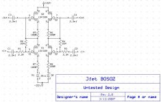
dw8083 said:Here's a first start at a design. Any thoughts? I'd like to get some feedback before building it. Source followers could be added.
-David
increase current (change J type,or use two or use another type of CCS);
after that -be careful with dissipation; decrease PS voltage ,if needed
edit:
R7 and R8 are in 10x magnitude bigger for my liking.........susy effect is smaller with them,degeneration is greater.........
for vinyl (next post,edit after):
Q2 and cousin are CCSes,cascodes,what you like?

OK folks,
I'll be the fool of the day and the one who asks the question that no one dares to ask...
What is the function of Q2 and how does it work?
Rüdiger
I'll be the fool of the day and the one who asks the question that no one dares to ask...
What is the function of Q2 and how does it work?
Rüdiger
dw8083 said:Thanks Choky for the insight.
This version has a second J511, lower voltage, and adjustments to R5-8. I would appreciate help in verifying the design and specifically in selecting values for R5-8. I think the values maybe a bit low.
Thank you,
-David
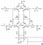
try like this
you must adjust R5 and R6 to catch J511's 4,7mA through each side
connection of J511 corrected and few other things
but,I usually make a mess............
edit:
move both 100K resistors to 2k2/22k node (not before 2k2 but after,ditto on gate)
Attachments
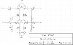
dw8083 said:Thanks Choky, I missed the wire between R7 & R8, it's now added. I'm still wondering if R5 & R6 are on the small side?
Here's the updated schematic.
-David
if your intention was to make CCS-es with two upper LSKs (hehehe) ,then you must look in data or test them ..........I don't know from top of my head what's Ugs for 4,7mA.............off course-you must match them,so you'll know then what resistors to choose
besides that-for later -you can add followers on output,naturally with overall feedback connected all around
edit:
if you are lazy for testing and matching,you can always send me handful of little critters and I'll do that for ya
Yes! Thanks Choky.
I noticed that Linear Systems how makes a version of the 2SK389, the LSK389.
Here's the data sheet:
http://www.linearsystems.com/datasheets/LSK389.pdf
-David
I noticed that Linear Systems how makes a version of the 2SK389, the LSK389.
Here's the data sheet:
http://www.linearsystems.com/datasheets/LSK389.pdf
-David
Zen Mod said:
if your intention was to make CCS-es with two upper LSKs (hehehe) ,then you must look in data or test them ..........I don't know from top of my head what's Ugs for 4,7mA.............off course-you must match them,so you'll know then what resistors to choose
besides that-for later -you can add followers on output,naturally with overall feedback connected all around
edit:
if you are lazy for testing and matching,you can always send me handful of little critters and I'll do that for ya
editedit:
I just saw your edit............
put them back (caps)
this way you don't have CCSes anymore.......in fact -heaven knows what you have like this

dw8083 said:Yes! Thanks Choky.
I noticed that Linear Systems how makes a version of the 2SK389, the LSK389.
Here's the data sheet:
http://www.linearsystems.com/datasheets/LSK389.pdf
-David
I know;
besides-you wrote LSK on schematic?
hehe,regarding handful.........am not picky.........2SK or LSK........
edit:
disregard my words about matching upper LSKs...........I just forgot that LSK is already pretty good matched😀 .............late night..........or I'm just bussy with coffee ?
I told ya that I make a mess often 🙄
I re-edited the edited post, and replaced the schematic with C1 & C2 moved back outside of the resistors.
BTW, Linear Systems calls their jfets LSK rather than 2sk, so I just went with it. 🙂
It is nice to see someone making these jfets again. They also have a 2sk170 replacement, LSK170 in all three current levels.
Thanks again Choky! You da man!
-David
BTW, Linear Systems calls their jfets LSK rather than 2sk, so I just went with it. 🙂
It is nice to see someone making these jfets again. They also have a 2sk170 replacement, LSK170 in all three current levels.
Thanks again Choky! You da man!
-David
dw8083 said:I re-edited the edited post, and replaced the schematic with C1 & C2 moved back outside of the resistors.
BTW, Linear Systems calls their jfets LSK rather than 2sk, so I just went with it. 🙂
It is nice to see someone making these jfets again. They also have a 2sk170 replacement, LSK170 in all three current levels.
....................
-David
yup,I know that........but I'm too far from US of A ,and Europe distribution is shalala.........and Europe is still not part of Serbia😎 ........I hope that these problems will be solved soon,at least for me 😉 (Paypal,here I come!!)

Thanks again Choky! You da man!
you're wellcome......if you ever read Castaneda (old goat brujo) you know what's behind my left shoulder.........
but -I have Papa somewhere behind my right shoulder......mostly to remind me how little I know
edit:
this days I must hack this site ,and switch >cool< to >devilr< ,so Papa will have adequate signature ..............
😎
dw8083 said:..............
I noticed that Linear Systems how makes a version of the 2SK389, the LSK389.
Here's the data sheet:
http://www.linearsystems.com/datasheets/LSK389.pdf
-David
btw- do you have them,and what's the price there?
dw8083 said:Chocky, YGM! -David
I don't know what this acronym is,but YT...........!
("you too" ,just in case
)OK- to stay on topic (strange for me........I'll try to not embrace that nasty habit...stayin' OnT)........
in your boots-I'll change that sisy two J511 sink to ,say ,two BJT sink,or any other "led referenced" sink........why do not use parts easy to find in every corner tobacco store,especially when it is probably even better than some fancy schmancy part..........as J511 certainly is
Well, now you have to build it! It should not be too tough to wire point to point.
Did you run this design on a simulator?
Do you plan on feeding it single ended or balanced? It seemed to me higher source resistance caused my 'almost stock' circuit to perform not so good at converting an unbalanced input to a balanced output.
I believe the original BZLS article showed much lower distortion with lower gain (from more source resistance). It also had a pot in between r7 and r8. This pot doesn't really work well as volume control, unless, perhaps, you are driving a unity gain amp or follower.
Just curious about your plans for this circuit, and hoping to see learn the best way to do unbalanced to balanced conversion.
JJ
jupiterjune said:Well, now you have to build it! It should not be too tough to wire point to point.
Did you run this design on a simulator?
Do you plan on feeding it single ended or balanced? It seemed to me higher source resistance caused my 'almost stock' circuit to perform not so good at converting an unbalanced input to a balanced output.
I believe the original BZLS article showed much lower distortion with lower gain (from more source resistance). It also had a pot in between r7 and r8. This pot doesn't really work well as volume control, unless, perhaps, you are driving a unity gain amp or follower.
Just curious about your plans for this circuit, and hoping to see learn the best way to do unbalanced to balanced conversion.
JJ
David or me?
me-not ..................hehe
David must do this ..............that's his homework
- Status
- Not open for further replies.
- Home
- Amplifiers
- Pass Labs
- Jfet Bosoz?