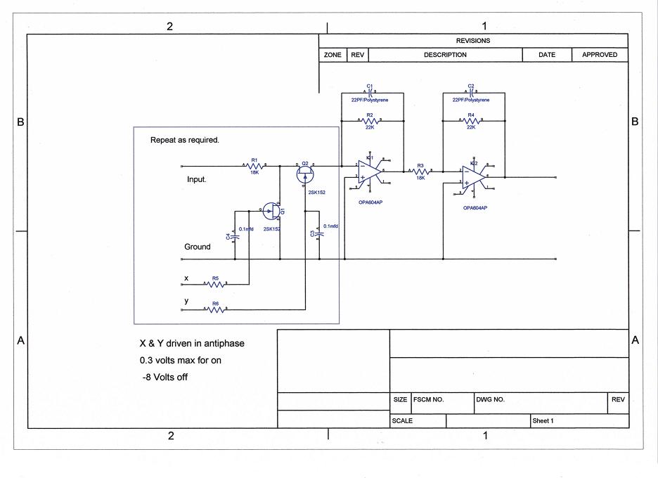
A gentleman and frequent contributor to this forum has kindly granted me permission to discuss a circuit he developed that uses JFETs to select/switch between audio sources.
The circuit (seen below) only shows one audio source, but the concept can be extended to multiple audio sources by replicating the portion of the circuit within the box marked "Repeat as required".
Using this concept with multiple input sources creates a virtual earth mixer, yet I don't think it was the really intended to be a mixer, but rather just a source selector.
My question is, what would happen if more than one source was selected? Would their be smoke or just the risk of some odd sounding music as the result of the mixing?
No smoke, I think.
This is a complicated circuit with 2 control voltages and an inevitable nonlinearity in the 'ON' jfet, however small. Plus there'll be some added noise. It's not really a good circuit. I'd much rather see a relay used. Primitive and electromechanical as they may be, they do have their advantages.
w
This is a complicated circuit with 2 control voltages and an inevitable nonlinearity in the 'ON' jfet, however small. Plus there'll be some added noise. It's not really a good circuit. I'd much rather see a relay used. Primitive and electromechanical as they may be, they do have their advantages.
w
Agreed. If relays aren't an option then I'd be happier with a 4052 CMOS logic IC handling 4 2-channel inputs than just plain JFETs.
A gentleman and frequent contributor to this forum has kindly granted me permission to discuss a circuit he developed that uses JFETs to select/switch between audio sources.
The circuit (seen below) only shows one audio source, but the concept can be extended to multiple audio sources by replicating the portion of the circuit within the box marked "Repeat as required".
Using this concept with multiple input sources creates a virtual earth mixer, yet I don't think it was the really intended to be a mixer, but rather just a source selector.
My question is, what would happen if more than one source was selected? Would their be smoke or just the risk of some odd sounding music as the result of the mixing?
Easy one first... there would be no smoke if more than one input were selected. The logic I use doesn't allow that though, but if it did it would just act as a mixer.
You might like to read more on it here starting at post #184 and particularly post 201 which explains it a little more and covers the main reasons why I used this method.
http://www.diyaudio.com/forums/soli...-amplifier-designed-music-10.html#post1560313
If I were doing it again I would this for the PIC controller I think,
FPRC5RX - DIY learning IR decoder
2nd time today I posted that link... it's a brilliant bit of programming and does exactly what the designer says. My PIC skills are pretty much zero I'm afraid but I programmed a PIC using the code in the above link and it's brilliant.
FPRC5RX - DIY learning IR decoder
2nd time today I posted that link... it's a brilliant bit of programming and does exactly what the designer says. My PIC skills are pretty much zero I'm afraid but I programmed a PIC using the code in the above link and it's brilliant.
Hi Mooly,
That PIC controller looks very cool, but I was going for something much more simple. Just a DPDT toggle switch to feed the required voltages to the gates of each pair of JFETs.
That PIC controller looks very cool, but I was going for something much more simple. Just a DPDT toggle switch to feed the required voltages to the gates of each pair of JFETs.
Using switches is easy. Just thinking out loud so if I make a daft mistake or comment lol...
I take it your using a split -/+ supply so set up two rails from the main opamp supply of say 8 volts and if possible another of around -0.3 volts. The 8 volt can come from a zener... the current needed is essentially zero and the -0.3 from a germanium diode (as I used) although I can't see why just resistive dividers couldn't be used if the supplies to the opamp are stable. Tie the gates to the -0.3v via say 2.2meg resistors... that put's both FET's off. Then use the switch to overide that by feeding the 8 volts via say 220k
I take it your using a split -/+ supply so set up two rails from the main opamp supply of say 8 volts and if possible another of around -0.3 volts. The 8 volt can come from a zener... the current needed is essentially zero and the -0.3 from a germanium diode (as I used) although I can't see why just resistive dividers couldn't be used if the supplies to the opamp are stable. Tie the gates to the -0.3v via say 2.2meg resistors... that put's both FET's off. Then use the switch to overide that by feeding the 8 volts via say 220k
Last edited:
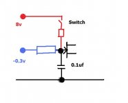
The 8 volt can come from a zener... the current needed is essentially zero and the -0.3 from a germanium diode (as I used) although I can't see why just resistive dividers couldn't be used if the supplies to the opamp are stable. Tie the gates to the -0.3v via say 2.2meg resistors... that put's both FET's off. Then use the switch to overide that by feeding the 8 volts via say 220k
This looks very good and uses less parts than what I was thinking about.
I can't wait to try this out. Hope my local toy store has what I need to test this baby out.
Thanks again Mooly!
Last edited:
Hi Mooly,
Please verify the voltage polarities for me. I thought an n-channel JFET would need 0.0 to say plus (+) 0.3 volts to turn on and a minus (-) 6.0 to (-) 8.0 volts to turn off. 😕
Please verify the voltage polarities for me. I thought an n-channel JFET would need 0.0 to say plus (+) 0.3 volts to turn on and a minus (-) 6.0 to (-) 8.0 volts to turn off. 😕
That's an N-channel jfet? That would make the control voltage polarities in the original diagram correct. If you take the gate of an N-channel jfet more than about 0.5V more positive than the source, then the gate-channel diode will conduct.
w
w
Thanks wakibaki,
I got twisted around when I looked at Mooly's original schematic that shows gate control voltages of +0.3 volts and -8.0 volts.
I got twisted around when I looked at Mooly's original schematic that shows gate control voltages of +0.3 volts and -8.0 volts.
Hope my local toy store has what I need to test this baby out.
You might find the JFET a bit tricky to source, its a Sony part. Doug Self's book 'Small signal audio design' has a whole chapter dedicated to signal switching circuits and goes into some depth with JFET switching arrangements. He prefers to use the J112 which is very widely available.
Thanks abraxalito,
It's nice to have choices!
I'll also say that the more I try to learn about JFET's the more I get confused. For example, here are specs for several popular n-channel JFET's that might be candidates in this application:
Datasheet for 2N3819: Vgs (off) = minimum not stated, maximum +8.0 Volts
Datasheet for BF245C: Vgs (off) = minimum -0.5 Volts, maximum -8.0 Volts
Datasheet for J112: Vgs (off) = minimum -1.0 Volts, maximum -5.0 Volts
So why do some of these have a positive Vgss (off) value and others are negative?
There's a very simple answer to this question 😀 Datasheets sometimes contain errors - you've found one in the Fairchild datasheet for the 2N3819. Onsemi's is just as bad. The correct (and most comprehensive) data is found in Vishay 2N3819
Thanks again abraxalito,
From now on I'll check the datasheet's from multiple manufacturers on any given part. 😱
From now on I'll check the datasheet's from multiple manufacturers on any given part. 😱
Good move. My working assumption is this - the datasheet containing the most details is going to be the source datasheet, thus the least susceptible to errors. The others will be copies.
Hi,
I wouldn´t recommend JFETs as swiching devices, especially not those named here. The 2N3829 for example features an Rds(on) of 150Ohms, the J112 50Ohms. What You want is a as low and linear-over-signal-voltage as possible device. I´d rather opt for a low Rds(on) MOSFET instead or a dedicated switch or multiplexer like the ADG- and DG-series of AnalogDevices or the 460x-series (and others) of Maxim.
jauu
Calvin
- Status
- Not open for further replies.
- Home
- Source & Line
- Analog Line Level
- JFET based audio source selector