Hello,
I have not seen this crossover discussed here at DIY Audio, and thought I would ask what your opinions are on this:
JFET Crossover Kit – Boozhound Laboratories
Manual and Schematic:
http://cdn.shopify.com/s/files/1/0289/4153/files/Boozhound_Laboratories_JFET_Crossover.pdf?73
I am thinking about giving it a shot as my first electronics project (apart from a set of passive crossovers I built).
My questions would be whether this is suitable as a first, to get my feet wet, and whether this circuit is in fact recommendable.
Attachments
change the bias voltage at the input.
Generate your half voltage using the two 1M or similar.
Then connect that to each jFET gate that requires a bias using a 220k
The input impedance seen by the source is then 220k+(1M||1M) = 720k
You can reduce the 1M significantly if that is required and the 220k holds up the input impedance.
Consider adding Buffers (same as the input) to each of the outputs. And add a resistor (to each output) to help isolate the cable capacitance from the active stage.
Last edited:
There is a modification to one of the filters, I can never remember which one.
Move the output tapping point to the Gate of the Follower instead of tapping into the Source. But only on one (maybe the Low Pass needs the mod).
There are some long Threads here discussing the jFET filter topology.
Also worth reading D.Feucht article on jFET Followers.
Move the output tapping point to the Gate of the Follower instead of tapping into the Source. But only on one (maybe the Low Pass needs the mod).
There are some long Threads here discussing the jFET filter topology.
Also worth reading D.Feucht article on jFET Followers.
Last edited:
Andrew, thank you very much for your comments.
I should have mentioned that I am pretty much a complete beginner when it comes to understanding circuit designs, and thus am a bit overwhelmed by your answer...
Are you saying that the Boozehound circuit is not optimal, and should be modified?
I was hoping that it would work as intended... I was looking for a good active crossover kit to build and use, and to just get a feel for the procedure of soldering components to a board. I am not yet ready to figure out how to modify these circuits (I am trying hard to learn, but had to start at zero, so it will take some time...)
I was looking for a good active crossover kit to build and use, and to just get a feel for the
procedure of soldering components to a board.
I would suggest starting with an op amp based crossover kit with pcb, since you are trying to get
some general electronics experience. Linkwitz-Riley is a popular circuit type, here's an example.
Two of these boards, and two wall warts, are needed for stereo. That said, the jfet crossover circuit
should be fine, especially if you substitute more reasonably priced available jfets.
Linkwitz-Riley 2-Way Active Crossover [XOVER-2] – Xkitz Electronics
Last edited:
I have been looking at that kit as well, but the Boozehound appeared to be a bit less comprehensive, there are fewer parts and more "space"...
Are there any other reasons why the JFET-based crossover might not be a good choice for me?
Are there any other reasons why the JFET-based crossover might not be a good choice for me?
+1 on 'rayma's suggestions.
I'd like to suggest the 'equal component value Sallen-Key' topology as a good place to start your understanding of active crossovers, but don't know if there are kits available. Roughly the same complexity and crossover slopes, but easier to source parts.
The circuit you asked about is clean, straightforward, and probably sounds pretty good, but has minor drawbacks that might be stumbling blocks for someone just starting out.
Good luck,
Rick
There is quite a range of xovers here, kits and ready made. I built the LR4 2.1, very happy with it Items in KMTech Design store on eBay !
Are there any other reasons why the JFET-based crossover might not be a good choice for me?
In both kits some of the parts are static sensitive, so work on a cookie sheet or aluminum foil sheet,
and keep touching the metal before and during handling both the parts and pcbs.
Do you have a good soldering pencil?
Last edited:
> work on a cookie sheet
Good practice; but JFETs are NOT as sensitive as MOS. The Gates are diodes and fairly robust.
Good practice; but JFETs are NOT as sensitive as MOS. The Gates are diodes and fairly robust.
Could you tell me what the drawbacks are?+1 on 'rayma's suggestions.
I'd like to suggest the 'equal component value Sallen-Key' topology as a good place to start your understanding of active crossovers, but don't know if there are kits available. Roughly the same complexity and crossover slopes, but easier to source parts.
The circuit you asked about is clean, straightforward, and probably sounds pretty good, but has minor drawbacks that might be stumbling blocks for someone just starting out.
Good luck,
Rick
Regarding the slopes: After experimenting a bit more with my old Pioneer D23 crossover, I am actually not sure anymore if I like a 12db slope at ~240Hz, where I want to set it. So maybe the 24db slope would be a better choice anyway.
I have seen those too, but I just thought the idea of using just JFETs is interesting and maybe better; the kit also has fewer components than others.There is quite a range of xovers here, kits and ready made. I built the LR4 2.1, very happy with it Items in KMTech Design store on eBay !
Thank you for the advice. I have an older blue one (don't know the brand, label has come off), it is good, but only 25W and quite a thick tip. I also have a Radioshack one, which is a bit loose everywhere... not so great, but it's 45W, which helped a lot when soldering thicker wires.In both kits some of the parts are static sensitive, so work on a cookie sheet or aluminum foil sheet,
and keep touching the metal before and during handling both the parts and pcbs.
Do you have a good soldering pencil?
Apologies. I must have gotten my neurons crossed when I read your thread starter -- somehow completely overlooking the 2nd link (with the Manual) and was imagining that you would build this up from just the schematic.
Now, I've read the manual and see that several issues are properly addressed, and won't give you trouble after all.
I like Boozhound and his philosophy, and don't want to publicly poop on his fine product. But there is one thing I gotta point out, as this design continues to proliferate: The frequency-setting values are wrong. They produce a filter that is over-damped -- more highly damped than even Bessel. A careful examination of the resulting FR shows a rounded corner, and a slope that never becomes straight. Attenuation an octave past the cutoff frequency is only around 9 dB; two octaves away its only 17 - 19 dB down.
I personally have a strong preference for more-damped-than-Butterworth filter profiles, but a lot of people don't -- esp if they don't find out 'til later that that's what they're getting.
Check member AndrewT's work on this. He built a fine 24 dB/octave two-way using the correct values, and it includes improvements.
Regards,
Rick
Attachments
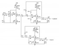
Ooops -- left out the best part:
cf3 must be twice the value of cf4, and
rf2 and rf3 parallel'd (as far as AC is concerned) form a value that is HALF each individual value; the value of rf1 must be HALF AGAIN that value at AC, of the combo of rf2 and rf3.
This will produce a filter slightly more damped than a 'maximally flat Butterworth' response.
Best luck,
Rick
Thank you for all your input. I am tempted, but a bit afraid that it might be a bit overwhelming for a first project.
I looked at the KMTech crossovers, and think that it may be a better place to start. With an assembled kit, I would only have to figure out the power supply part and connectors. Well, and possibly learn how to change resistors if I want to change the x-over point(s).
Nevertheless, if I would eventually use a circuit as e.g. AndrewT's, should I design and order a PCB for it, or could one actually put this together on a "breadboard"?
I put together a bass only Low Pass filter for an LR4 with the RCRC PSU filtering and input and output Followers/Buffers on a piece of strip board approximately 1" by 1"
and powered that with a twisted triplet from the +-50Vdc main PSU.
But it is all so "crammed in" that is is nearly impossible to debug if there is an assembly fault.
and powered that with a twisted triplet from the +-50Vdc main PSU.
But it is all so "crammed in" that is is nearly impossible to debug if there is an assembly fault.
Hi,
one should not forget that the filter should suit the driver's requirements.
So far I haven't seen a textbook folter that does.
Neither Butterworth, Chebycheff, Linkwitz nor Waldorf&Statler do, simply because they don't care about the amplitude response of the driver.
The acoustic response of the driver will never follow Butterworth or any other textbook flavour.
Passive crossovers are designed different, with the driver in mind, meaning that in trying to achieve a certain target response they are tuned to equalize the drivers response at the same.
No active xover -regardless of how perfect it may follow a certain topology- will sound optimal if it doesn't contain some means of equalization for the driver.
Now some xovers simply add the eq-circuitry and become quite complex .... and if done with OPAmps as it seems soo convinient ... its guaranteed to sound cold, sterile, terrible.
If You design the active filter just the way You'd design a passive one, it'll suit the driver, it'll may require a considerably lower active parts number count, and it certainly will sound better.
If that requires a slightly peaking response from the filter instead of a soft rounded one, so let it peak. 😛
jauu
Calvin
Last edited:
Boozehound's circuit only provides 12 db/octave rolloffs, which means that the LP and HP outputs will be out-of-phase. Better to use 24db/octave filters, which eliminates that problem.
I understand very much what your concern is. Personally, I have noticed quite a big difference between using an active vs. a passive crossover, so much, that I am convinced that the active path is a better alternative.Hi,
one should not forget that the filter should suit the driver's requirements.
So far I haven't seen a textbook folter that does.
Neither Butterworth, Chebycheff, Linkwitz nor Waldorf&Statler do, simply because they don't care about the amplitude response of the driver.
The acoustic response of the driver will never follow Butterworth or any other textbook flavour.
Passive crossovers are designed different, with the driver in mind, meaning that in trying to achieve a certain target response they are tuned to equalize the drivers response at the same.
No active xover -regardless of how perfect it may follow a certain topology- will sound optimal if it doesn't contain some means of equalization for the driver.
Now some xovers simply add the eq-circuitry and become quite complex .... and if done with OPAmps as it seems soo convinient ... its guaranteed to sound cold, sterile, terrible.
If You design the active filter just the way You'd design a passive one, it'll suit the driver, it'll may require a considerably lower active parts number count, and it certainly will sound better.
If that requires a slightly peaking response from the filter instead of a soft rounded one, so let it peak. 😛
jauu
Calvin
Nevertheless, EQ'ing may be necessary, especially if you are trying to put together an open baffle speaker, which is what I am trying to do. What I ended up doing is exactly what you are describing as eq'ing—only that I used a parametric equalizer to compensate for the open baffle roll-off, as well as some minor adjustments of the drivers irregularities. These were all just experiments, on some ugly, quickly put-together baffles, but the results were great...
My goal is to continue this path. To use the parametric EQ I bought (Klark Teknik D410), and an active crossovover after it.
So far I had done all my experiments with an old Pioneer D23 active crossover. While the D23 is a really cool piece of vintage equipment, I felt it was somewhere lacking transparency, maybe (due to age) even distorting a bit. It also does only offer 6/12/18db crossovers, no 24db crossovers.
Today I decided to go another route—I used my computer with it's Xonar XD2 soundcard, together with a crossover software plugin, to simulate a 24db LR crossover digitally. I wanted to see whether it works, how it sounds. I was quite impressed... the balance in my three-way setup was now much better, no more distortion of any kind; if anything was worse, it was maybe that the bass lacked a bit of "attack", which seemed to be better with the analog EQ as opposed to the digital one.
My point now is, that I believe that I can put together a system with analog 24db LR crossovers and the PEQ that I would certainly be happy with. I prefer this over the all-digital route, since I use vinyl and wouldn't like the A/D, D/A, A/D conversion, and also because I simply feel that the analog way can still sound a bit more "real".
So the plan is pretty much set, I want to send my pre-amp signal to the Klark-Teknik EQ, from there to a "box" with two KMTech 3-way active crossovers, and from there to the low/mid/high amps and speakers.
I just need to figure out how to put this all together now... which power transformer to buy, which PSU etc... hopefully I will find help here 🙂
Yes, that was one of my concerns. And after trying a digital 3-way with 24db LR filters, I think the 24db roll-off sounds best for my setup, and I will most likely use the KMTech 3-way crossover for this project...Boozehound's circuit only provides 12 db/octave rolloffs, which means that the LP and HP outputs will be out-of-phase. Better to use 24db/octave filters, which eliminates that problem.
Boozehound's circuit only provides 12 db/octave rolloffs, which means that the LP and HP outputs will be out-of-phase. Better to use 24db/octave filters, which eliminates that problem.
This is a drastic over-simplification of phase relationships in a speaker system. If a 2nd order xover puts the drivers 180 out of phase, reversing the leads of either driver solves the problem PERFECTLY. A 4th order xover is no better at eliminating phase issues than any other xover type.
The reason is that, just as drivers have their own FR curves, they also have their own phase. Calvin touched on the issue above, but most people still don't understand. An active xover solves only two problems that passives cannot: it eliminates the effect of the driver's impedance on the filter's response, and it couples the driver directly to the amp. It does NOTHING to reduce FR irregularities or phase relationships of the drivers themselves, regardless of the order of the filter.
Any two drivers must sum acoustically at the crossover point, and they should be similar in phase for an octave or more if possible around the xover point. An active filter, no matter the order, does not eliminate this problem. If either driver is out of phase with its mate in the "raw" unfiltered state, any xover will not fix that unless it is designed to do so. A 4th order LR will not ADD any other phase distortion at the xover point, but neither will it eliminate any that was present to begin with. It is the single most common misperception about active xovers, or about xovers in general. There are strong parallels between designing a system with passive xover and active xover. The basic acoustic problems do not just go away.
By the way, that eBay kit doesn't impress me at all. It looks to have really cheap parts that will produce mediocre sound, and very little flexibility for proper implementation. Check out ESP P09 kit, which is a much more versatile design and has excellent support from the designer.
Peace,
Tom E
Which one of the eBay kits are you referring to, the one from KMTech or the one from XKitz?By the way, that eBay kit doesn't impress me at all. It looks to have really cheap parts that will produce mediocre sound, and very little flexibility for proper implementation. Check out ESP P09 kit, which is a much more versatile design and has excellent support from the designer.
- Status
- Not open for further replies.
- Home
- Source & Line
- Analog Line Level
- JFET active crossover from Boozehound?