Hi Michael,
Interesting indeed, particularly when your "on-axis SPL at 4m distance" response is compared to the Hornresp far-field directivity response for the same system 🙂.
...
David

Hello David and Michael,
For me, the picture is more clear now.
... Thank you for your contribution....
######
There still a small difference between the response simulated by Hornresp and by Axidriver in the high frequency part of the response (above 2kHz for the example shown) as the reponse predicted by Hornresp fall more quickly.
Jean-Michel, David – if you are into minute details - I think there are several parameters regarding coil impedance in AxiDriver I haven't looked into in detail yet (no need until now with ruler flat AMT impedance and me mainly being interested in the horn alone 😉 )
Do you have a measurement of the TAD coil impedance ?
Michael
Hello Michael,
Here is a .txt file with the impedance curve of the TD2001 as measured by me on a Le Cléac'h horn with Fc = 320Hz
Best regards from Paris, France
Jean-Michel Le Cléac'h
Here is a .txt file with the impedance curve of the TD2001 as measured by me on a Le Cléac'h horn with Fc = 320Hz
Best regards from Paris, France
Jean-Michel Le Cléac'h
mige0 said:Do you have a measurement of the TAD coil impedance ?
Attachments
Last edited:
This is the best I could get
- peak seems to be to low Q and the second hump in your measurements (around 1800Hz) isn't there (where this one comes from?)
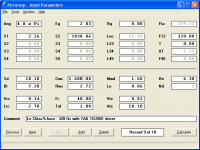
Values entered in AxiDriver 160Hz Horn - but should be driver only, if I understand correctly:
Fs 320 Hz
Qms 1.2
Qes 0.39
BL 7.25 N/A
Mms 1.61 g
Cms 1.53 E-4 m/N
Rms 2.71 Ns/m
http://www.audioasylum.com/forums/hug/messages/12/128658.html

Michael
- peak seems to be to low Q and the second hump in your measurements (around 1800Hz) isn't there (where this one comes from?)
Values entered in AxiDriver 160Hz Horn - but should be driver only, if I understand correctly:
Fs 320 Hz
Qms 1.2
Qes 0.39
BL 7.25 N/A
Mms 1.61 g
Cms 1.53 E-4 m/N
Rms 2.71 Ns/m
http://www.audioasylum.com/forums/hug/messages/12/128658.html
Michael
Last edited:
Hello Michael,
Here is a .txt file with the impedance curve of the TD2001 as measured by me on a Le Cléac'h horn with Fc = 320Hz
Best regards from Paris, France
Jean-Michel Le Cléac'h
Hi Jean-Michel and Michael,
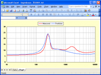
Attached are details of the input parameter values I am using in Hornresp for the 320Hz Le Cléac'h horn and TAD TD2001 driver, together with a comparison of the .txt file measured impedance versus Hornresp prediction.
Kind regards,
David
Attachments
Hello Michael,
The impedance curve of most compression drivers often shows several impedance peaks.
As an example give a look to the impedance curve of the JBL2445 compression driver mouted on the biradial horn reference 2380:
http://www.jblpro.com/pub/components/2445J.pdf
For the TD2001 the bump in the impedance curve around 1900Hz is related to a cavity resonance as explained in Kinoshita's paper about the design of the TD2001 driver.
JAES convention 1978
preprint N°1422 (M2)
The influence of parasitic resonances on compression driver loudspeaker performance.
By Shogo Kinoshita and Bart Locanthi...
You'll find in attached file a graph explaining the origin of that resonance.
Best regards from Paris, France
Jean-Michel Le Cléac'h
This is the best I could get, peak seems to be to low Q and the second hump in your measurements (around 1800Hz) isn't there (where this one comes from?)
Attachments

It might be necessary to shape the back side of the diaphragm and allow radiation on both sides of the diaphragm during simulation.This is the best I could get
- peak seems to be to low Q and the second hump in your measurements (around 1800Hz) isn't there (where this one comes from?)
Values entered in AxiDriver 160Hz Horn - but should be driver only, if I understand correctly:
Fs 320 Hz
Qms 1.2
Qes 0.39
BL 7.25 N/A
Mms 1.61 g
Cms 1.53 E-4 m/N
Rms 2.71 Ns/m
High Efficiency Speaker Asylum - Hornresp and TD2001 simulation - Jmmlc - November 06, 2007 at 03:34:29
Michael
ALL compression drivers exhibite two peaks on any horn including a plane wave tube. It is not due to a "cavity resonance" (if it were then some drivers would have it and some wouldn't) but it is in fact due to the air compliance between the diaphragm and the phase plug. If you draw out the lumped paranmeter circuit you will see that a compression driver has the exact same topology as a single bandpass loudspeaker enclosure, which also has two peaks in its impedance curve. SPEAK will show this very clearly.
Hello Earl,
What you wrote about the resonance in the small volume between the diaphragm and the phase plug is true and is probably responsible of impedance anomalies at higher frequency. IMHO such effects can be taken in account by hornresp (and others as Akabak).
Many compression drivers measured on plane wave tube show more than 2 peaks on the impedance curves (because other sources of resonances may exist in compression drivers other than the 2 mentionned by you and Kinoshita)
But the cavity effect mentionned by Kinoshita for the TD2001 according to his paper is not questionable and is also at the origin of the hole at 1900Hz for which the TD2001 is famous for.
In attached file the correlation between the impedance curve and the frequency response curve of a TD2001 (voltage driven) mounted on a Le Cléac'h horn. Every feature in the impedance curve possess its "inverse" on the frequency response curve... this is most probably not a random effect.
Best regards from Paris, France
Jean-Michel Le Cléac'h
ALL compression drivers exhibite two peaks on any horn including a plane wave tube. It is not due to a "cavity resonance" (if it were then some drivers would have it and some wouldn't) but it is in fact due to the air compliance between the diaphragm and the phase plug. If you draw out the lumped paranmeter circuit you will see that a compression driver has the exact same topology as a single bandpass loudspeaker enclosure, which also has two peaks in its impedance curve. SPEAK will show this very clearly.
Attachments
Last edited:
Maybe similar cavity here:
http://www.diyaudio.com/forums/full-range/125666-bandor-50-sw8-modules-measurement.html#post1551394
http://www.diyaudio.com/forums/full-range/125666-bandor-50-sw8-modules-measurement.html#post1551394
As I recall the Bandors have a much flatter dust cap than the jordans, so yes, that's about right. The Jordans don't show the dip due to the shape of the cap.
Doreen said once it's voice coil material CCAW vs. pure copper. She's going to send me 12" and 15" cones. I'll do the rest. As usually with Bandor it goes very slow 😉
The older Bandor baskets were not of one casting, and the weight of the magnet would cause it to misalign resulting in rubbing coils. A friend had also had some problems with aluminum coil cold soldering. So you'd probably want to check what improvements have been made.Doreen said once it's voice coil material CCAW vs. pure copper. She's going to send me 12" and 15" cones. I'll do the rest. As usually with Bandor it goes very slow 😉
Nothing has changed that's why I prefer my chassis. Off course I'll experiment when her grandson hopefully make them.
Hi Jean-Michel and Michael,
Attached are details of the input parameter values I am using in Hornresp for the 320Hz Le Cléac'h horn and TAD TD2001 driver, together with a comparison of the .txt file measured impedance versus Hornresp prediction.
Kind regards,
David
Is the plateau right side of the resonance peak in your simu due to the horn's performance, or did you enter special motor parameters for that ?
.....but it is in fact due to the air compliance between the diaphragm and the phase plug.
Wouldn't that only up-shift resonance frequency ? – how comes this forms a resonance (in the audio band) given the low dimensions involved (single digit mm range) - or do you include the canals here?
It might be necessary to shape the back side of the diaphragm and allow radiation on both sides of the diaphragm during simulation.
Have you ever tried to model a volume behind the diaphragm ?
Hello Michael,
The impedance curve of most compression drivers often shows several impedance peaks.
.....The influence of parasitic resonances on compression driver loudspeaker performance.
By Shogo Kinoshita and Bart Locanthi...
You'll find in attached file a graph explaining the origin of that resonance.
Strange this tiny volume the VC is diving into adds more than mere compliance...
Michael
Last edited:
Hello Earl,
What you wrote about the resonance in the small volume between the diaphragm and the phase plug is true and is probably responsible of impedance anomalies at higher frequency. IMHO such effects can be taken in account by hornresp (and others as Akabak).
But the cavity effect mentionned by Kinoshita for the TD2001 according to his paper is not questionable and is also at the origin of the hole at 1900Hz for which the TD2001 is famous for.
Jean-Michel Le Cléac'h
I never said that the cavity resonance does not exist in that driver, it does, and in many others as well. I said that it was NOT the reason for the second peak, which is what you stated and was incorrect. The cavity resonance will only be a very small perturbation on the voice coil impedance because it does not have a strong effect on the voice coils motion even though it can have a large acoustic effect.
I am curious, then what is the cause? Measurements on these types of drivers have been done in vacume chambers, and the higher frequency hump disappears.I never said that the cavity resonance does not exist in that driver, it does, and in many others as well. I said that it was NOT the reason for the second peak, which is what you stated and was incorrect. The cavity resonance will only be a very small perturbation on the voice coil impedance because it does not have a strong effect on the voice coils motion even though it can have a large acoustic effect.
With cone drivers, yes. Yesterday I tried with only a dome, but it AxiDriver did not allow back side radiation for that configuration. Very odd. I guess it simplifies the math modeling for the software....
Have you ever tried to model a volume behind the diaphragm ?
Michael
I am curious, then what is the cause? Measurements on these types of drivers have been done in vacume chambers, and the higher frequency hump disappears.
Of course!! Just as it should. The air compliance in front of the diaphragm is gone hence so is the resonance and the double peak.
In this case, I think both of you are in agreement, but just different use of terminology.Of course!! Just as it should. The air compliance in front of the diaphragm is gone hence so is the resonance and the double peak.
How would one explain compression drivers not having a dip at the frequency of second peak of higher frequency?ALL compression drivers exhibite two peaks on any horn including a plane wave tube. It is not due to a "cavity resonance" (if it were then some drivers would have it and some wouldn't) but it is in fact due to the air compliance between the diaphragm and the phase plug. If you draw out the lumped paranmeter circuit you will see that a compression driver has the exact same topology as a single bandpass loudspeaker enclosure, which also has two peaks in its impedance curve. SPEAK will show this very clearly.
- Home
- Loudspeakers
- Multi-Way
- Jean Michel on LeCleac'h horns