Dear all,
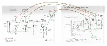
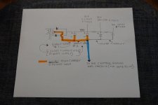
I have built an amp based on the JE Labs 300b design and I would very much appreciate some advice on the grounding technique. I have wired the amp physically as shown (the red/green power send and return are twisted in practice) with the intent of keeping the most sensitive stage furthest from the chassis connection.
Is there any way in which I can improve this? All comments and suggestions gratefully received.
Attachments
1. Reduce the ground loops:
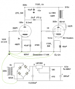
Always connect the B+ center tap Directly to the First filter cap negative.
Then, connect a second wire from the first filter cap negative to the second filter cap negative.
Connect a 3rd wire from the second filter cap negative to a central ground point.
Connect all the other filter caps to the central point ground.
Connect the isolated RCA phono input jack return to the volume control return and the input triode self bias resistor return.
Connect another wire from that point to the second triode self bias RC network return.
Connect a third wire from there to a central ground point.
Connect the 300B self bias RC network return to the central ground point.
Connect the central ground point to the metal chassis.
2. Filament hum and intermodulation
I have never used a DHT input tube, but . . .
You have chosen a DHT input tube. I recommend a DC filament supply.
The 6SN7 should have two 100 Ohm resistors, one from one filament end to ground, and the other from the other filament end to ground.
Some 300B tubes have hum, even if you adjust the 50 Ohm potentiometer to best position.
I use DC filaments on the 300B.
DC filaments also eliminates the Intermodulation caused by DHT AC filaments.
3. Magnetic Coupling:
The single ended output transformer (OPT) needs to be spaced away from the B+ chokes, and power transformer. And the OPT laminations needs to be at right angles versus the chokes and power transformer.
Do not use a magnetic steel chassis. It transmits the magnetic fields from the chokes and power transformer to the OPT.
The above are just my opinions.
Your mileage may vary.
Last edited:
6a3 - that's very useful. Could you add a post for my benefit, also for a 300b SE?
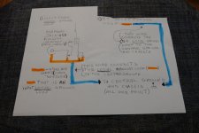
In my case I have a separate PSU and signal chassis. The PSU is just for the HT and should be simple - connect all the grounds to a star point.
The signal chassis also contains the heater supplies, or filament in the case of the 300b which are DC floating anyway. The heater supply is DC via a voltage reg, and that has a ground to connect.
And what of hum issues when connecting a PSU with HT to a signal chassis with heater supplies? Two mains connections?
I'm attaching a specimen grounding for a 6SN7 to EL12n amp. The 6SN7 doesn't need DC heating but this is just for reference. The AC heating for the EL12n would have a virtual centre tap to ground via resistors.
Attachments
Last edited:
updated scheme
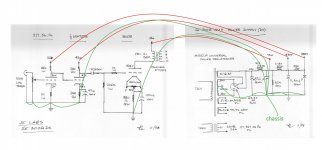
Many thanks - so if I have understood correctly, you would recommend the attached.
I assume the advantage here is that the first input tube ground goes directly to the star, so that it can never be contaminated by large pulses from elsewhere. The disadvantage, I suppose, is that the power/ground to the first tube cannot be twisted any more.
Attachments
andyjevans,
That is a good question, how to prevent hum with a split chassis application.
I have never designed, built, or owned an amplifier with a separate power supply chassis and a separate amplifier chassis.
I will have to think about all the effects of the many potential ground loops.
Perhaps I will come up with some factors to consider, and tradeoffs of different methods to reduce the ground loops.
It probably will take me some thought off and on for a few days, or a couple of weeks.
Perhaps some others who have made split chassis work well will give us their comments.
One separate issue of putting B+ on a second chassis is the Safety Considerations.
1. A cable probably should consist of wires, covered by a mesh shield, covered by plastic.
2. The connectors at both ends of the cable, and the connectors on the two chassis needs to be so that if the cable comes out at one end, there are no exposed conductors on the power chassis, and the two cable end connectors.
Safety First!
"Prevent the Surviving Spouse Syndrome."
ebuckley002,
I think my best way to show the principles of what I do to reduce ground loop effects is to do some drawings of my own, and then scan them, and put them up on this thread.
Give me some time to get it done, perhaps over a few days or couple of weeks.
I think my best way to show the principles of what I do to reduce ground loop effects is to do some drawings of my own, and then scan them, and put them up on this thread.
Give me some time to get it done, perhaps over a few days or couple of weeks.
Andy,
the only time I have used a split chassis, I used locking (i.e. bayonet) connectors.
kind regards
Marek
edit - and the connectors were handed, so it was impossible to miswire/mishandle or force a connection that was "wrong".
the only time I have used a split chassis, I used locking (i.e. bayonet) connectors.
kind regards
Marek
edit - and the connectors were handed, so it was impossible to miswire/mishandle or force a connection that was "wrong".
Last edited:
If you haven't bought that small dedicated filament transformer yet.... Id suggest getting a split bobbin type rather than a regular one with overlapped secondary. Its really made a difference in some things I'm breadboarding lately. About the same cost. But they really do block common mode hum, and they don't need shielding or modifications to shield it.
Perhaps a sensible way for people to draw schematics would be to label each end of the ground and power wires A & A', B & B', etc, so it becomes obvious what each end is connected to.
Thus a star ground might be labelled "C-D-H-J" for example and the four things connected to the star ground would have labels C', D', H' and J'. It might also be sensible not to use B or F to not confuse labels with the power supply or filament.
kind regards
Marek
Thus a star ground might be labelled "C-D-H-J" for example and the four things connected to the star ground would have labels C', D', H' and J'. It might also be sensible not to use B or F to not confuse labels with the power supply or filament.
kind regards
Marek
ebuckley002,
I am attaching 3 drawings that illustrate some of the ways I reduce ground loops in my tube amplifiers.
A wire is not a wire; instead it has resistance, no matter how small; and it has inductive reactance, no matter how small. Current through a wire creates a voltage, no matter how small.
That voltage can be induced into various circuits of the amplifier.
Ground loop currents need to be kept local, and after that, each loop can be connected to a single point. That single point is the central ground point, and is also connected directly to one and only one point on the chassis there at the central ground point.
The input stage is the most sensitive; the B+ supply input capacitor has the highest currents, and fastest transients (high frequencies), and the output stage needs attention so that its currents do not get into the input.
I hope some of you find this useful.
Attachments
Last edited:
andyjevans,
I have not come up with very many ideas of how to deal with ground loops for an amplifier that has two chassis, one for the power supply, and one for the amplifier.
Never built an amplifier that way.
I prefer to build mono-blocks, with each mono-block complete unto itself.
But here goes . . .
I think that each chassis should connect to a 3 wire power mains, if possible. Connect the IEC socket ground connection to the central ground point, which is also the one and only connection to that chassis.
Both power supply chassis power cord, and amplifier chassis power cord should be plugged into the same power strip, and connect the mains grounds to each chassis.
Using 3 wire IEC power cords and IEC sockets makes this easy.
This should be followed whether the power transformers are all on the power supply chassis, or whether perhaps the filament transformers and/or bias power transformers are on the amplifier chassis.
Safety first!
You should have enough outlets on the power strip to plug in the signal sources too. (whether they are 2 wire or 3 wire power cords). Turntable, phono preamp, preamp, tuner, CD player; any of these you have should be plugged in there. 2 wire power cords may have to be plugged in one way or the other to reduce ground loops, unless they have one broad spade and one narrow spade . . . and the power strip should only allow those 2 wire broad spade/narrow spade coded plugs to be plugged in only one way.
Try to make all B+, Bias Supplies, input circuits, and output circuits have their own local ground loops, then use separate wires for each of those local ground loops to connect to the central ground (which is also the chassis).
I hope that gives you some ideas of how to start (you may have to modify to get it to its best performance).
andyjevans,
I have not come up with very many ideas of how to deal with ground loops for an amplifier that has two chassis, one for the power supply, and one for the amplifier. Never built an amplifier that way. I prefer to build mono-blocks, with each mono-block complete unto itself. But here goes . . .
Thanks for that. Much appreciated. I'll study it and may ask some questions later.
Yes.
Chokes should not be close to the power transformer. And not close to the input tube. The first cap in the PS, after the rectifier, should be as close to the power transformer CT. Eventual star ground should be near the catode of the input tube. (not near the input RCA). IF it is posibile Every ground wire should be connected in that central ground close to the catode of input tube.
Other concept is to use 2 ground planes one with close to catode "audio" point, other "power" close to the CT of power transpfrmer. Then just connct thhese 2 grounds. (Sakuma style.)
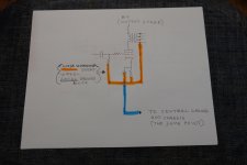
BUT in the topology like on first post we have 3 active stages, that leed to phase inversion at the primary OT. So the secondary should be inverted for phasein=phaseout.
In that case do not connect OT - to the ground but to +speaker conn and + to -speaker conn at the amplifier speaker jacks.
Chokes should not be close to the power transformer. And not close to the input tube. The first cap in the PS, after the rectifier, should be as close to the power transformer CT. Eventual star ground should be near the catode of the input tube. (not near the input RCA). IF it is posibile Every ground wire should be connected in that central ground close to the catode of input tube.
Other concept is to use 2 ground planes one with close to catode "audio" point, other "power" close to the CT of power transpfrmer. Then just connct thhese 2 grounds. (Sakuma style.)
BUT in the topology like on first post we have 3 active stages, that leed to phase inversion at the primary OT. So the secondary should be inverted for phasein=phaseout.
In that case do not connect OT - to the ground but to +speaker conn and + to -speaker conn at the amplifier speaker jacks.
Zoran,
The signal source (example CD player, tuner, phono preamp, control preamp) can form a ground loop with the power amplifier input tube circuit.
That is exactly why I recommend that the power amplifier design does the following:
Insulate the RCA input connector from the chassis (use plastic insulating washers).
Use very short wires from the RCA input connector return connection, to the input grid resistor return connection, and the input cathode's self bias resistor's return connection (and if present, the self bias bypass cap's return connection).
That reduces the input stage ground loop effect.
After making that short ground loop, connect that to the central ground point.
That is the way I do it for less than 100uV hum at the amplifier output (4 or 8 Ohm taps).
Many other person's Hi Fi system components, power mains, etc. may require a different method.
. . . Your Mileage May Vary.
Insulate the RCA input connector from the chassis (use plastic insulating washers).
Use very short wires from the RCA input connector return connection, to the input grid resistor return connection, and the input cathode's self bias resistor's return connection (and if present, the self bias bypass cap's return connection).
that is the must to do, insulated input conn near ti the input tube and near that point connect to the chasses - not in the area of power conn
I try to sad this pretty much the same as You propose. 🙂
Something I left out is the wiring dress.
Extreme examples:
1. Consider the B+ secondary center tap wire that connects to the first capacitor negative terminal.
Then, if the input tube circuit's return wire to the central ground point is parallel to the
B+ center tap wire . . . you have created a 1 turn primary and 1 turn secondary air transformer.
The high current/high frequency transients of the B+ circuit will be transformed into the most sensitive part of the amplifier, the input stage (even though it is just the ground return wire).
This is a form of magnetic coupled interference.
2. One of the two B+ high voltage secondary wires (not the center tap wire) is placed close to the RC coupling cap that connects from the driver tube's plate to the output tube's control grid.
That will cause capacitive coupling from the high voltage AC to the grid of the output tube.
Most wiring dress are not done this badly, but lesser mistakes may still cause hum problems.
Last edited:
It has been quite a while since I built me JE labs 300b but the way they originally ran the ground as a large bare wire above all the components terminated on one end at the power supply. This is the way I did mine and it was quiet. It was a nice simple design that had a purity combined with some efficient horns that has haunted me since I built it. The next closest I have come to it is a pass f4 with a pair of frugal horns.
Bill
Bill
Last edited:
- Home
- Amplifiers
- Tubes / Valves
- JE Labs 300b grounding advice