Interesting, can you help me learn more ? ....The input device develops a voltage across R3 which is fed to the base of the phase splitter/driver device. But R19 kind of gets in the middle here, not sure the rationale for R19?
And I don't understand how this design is different from JLH other than the Darlington outputs - the JLH itself does not go nicely into ClassB so what is different here that I've missed which makes this suitable for use with low bias current ?
Good question! R19 is only for modeling and test purposes, otherwise it is difficult to know the current through this section of wire or how ripples will affect the performance. In the real implementation R19 should be replaced by a jumper. The JC2012 output stage is composed of a Darlington pair which allows the amp work in class-B. Hood's 1969 design is not able to do so. In other words, if you bias the JC2012 in class-B(typically 30mA), it works almost as good as a class-A, but the power efficiency is around 70%. However, if you under bias Hood's 1969 design, you will get serious distortion.
And I don't understand how this design is different from JLH other than the Darlington outputs - the JLH itself does not go nicely into ClassB so what is different here that I've missed which makes this suitable for use with low bias current ?
Its not different, its just Darlington. The drivers in the Darlington
pairs are still JLH Class A (at a much lower quiescent than usual),
the output of the Darlington pairs are current dumpers in class B.
Nothing wrong or cheating about this solution except calling such
pairs with two transistors and two resistors apiece "discrete".
By such reasoning, I can design an entire JLH headphone stage
from one 74LS04 hex inverter and thereby call it one "discrete".
And yes, I actually did that sometime back, intended only as a
joke. But look sometime the internal schematic of that chip and
tell me it isn't JLH, just waiting for a feedback loop to be closed...
Good that SRJLH2012 will have competitor. A + B was not one
of the output classes I had tried for yet. My closest maybe non-
switching AB+CCS. My quiescent current for CCS bypass alone
is usually set much higher. Turning the transistors hard off is
always going to be more efficient than bleeding them a trickle...
Last edited:
The JC2012 is essentially a Death of Zen with Darlington outputs. The DoZ is similar to the JLH but swaps a CCS for a driver, with bootstrapping added to drive the upper half. Both concepts have their problems with load immunity, though in case of a Class A headphone amp the JLH gave better simulated performance due to higher O/L gain. B/AB operation is a different story.
McIntosh2100 I repaired recently had three identical output transistors.
First one in class A was driver for the other two in class B, all in parallel.
This was a Darlington arrangement, not terribly different.
I think Gm doubling of the crossover was ending just as the twin B's
were kicking in (again with double Gm), and current through the A
began to limit upon a constant current that bypasses the B emitters.
Thus the Gm wasn't ever tripling, even with three transistors. They
had somehow conspired to keep the Gm more or less constant at the
sum of two transistors...
That would probably be an ideal output arrangement for this one too.
But then again, perhaps it is non-linearity of Gm in the Darlingtons
that permits quiescent to be shaped so low. Depends which feature
you consider to be of greater Merit. You have choices...
Last edited:
Hi sg. could you post the schematic of the Death of Zen? Thanks.The JC2012 is essentially a Death of Zen with Darlington outputs. The DoZ is similar to the JLH but swaps a CCS for a driver, with bootstrapping added to drive the upper half. Both concepts have their problems with load immunity, though in case of a Class A headphone amp the JLH gave better simulated performance due to higher O/L gain. B/AB operation is a different story.
Its not different, its just Darlington. The drivers in the Darlington
pairs are still JLH Class A ...
The "discrete semiconductor" used in my post is antonym to "integreted chip". I do not want to force anybody to agree that a darlington transistor is a "discrete semiconductor". If a darlington transistor cannot be called "discrete" then what about a mostfet with a diode in it? My purpose is to present the design to other DIYers who care to get better sound with improved design at lower cost. I believe DIYers won't care a darlington is a "discrete" or "integrated", they just use it as a transistor.

All the design philosophy good and
fine, but "Discrete". Seriously???
I wasn't gonna, but you force me.
Integrated, the new discrete!
Dashed box and everything...
Sorry, I'm like so 5min ago, I did
not realize definition had changed.
fine, but "Discrete". Seriously???
I wasn't gonna, but you force me.
Integrated, the new discrete!
Dashed box and everything...
Sorry, I'm like so 5min ago, I did
not realize definition had changed.
Attachments
Last edited:
Hi,Hi sg. could you post the schematic of the Death of Zen? Thanks.
Death of zen is in Rod Elliot site .
There is another variant of the DOZ in this thread.
http://www.diyaudio.com/forums/solid-state/208076-death-zen-15-watt-power-amplifier.html
I am building this schematic now .
thanks
kp93300
Member
Joined 2009
Paid Member
The JC2012 output stage is composed of a Darlington pair which allows the amp work in class-B...
ah, I think I see what you are doing. You have a JLH Class A, the output is connected to the load and you have in parallel a pair of power devices biassed in Class B also connected to the load whilst being steered by the Class A drivers. Broskie might call it an 'impedance converter'.
what are the advantages over a 'regular' quasi complementary output stage ?
It is good to see people being adventurous/ exploring Linsley-Hood's circuits.
I am running a 1996 Class A and am content with that even if it does give off a bit of heat which doesn't suit everyone.
For interests sake I was wondering if anyone has seen, or has views on, the all NPN output stages used by ON Semiconductors in many of their IC's (e.g. MC33078) and whether or not these are suitable to be upscaled for a more efficient power amplifier.
On Semi make some impressive claims for this configuration.
At a glance the version of the JLH Class A amplifier with constant current source might be adapatable. MC33078 uses a phase splitter as per JLH in combo with a new take on enhanced quasi comp outputs.
mjona
What I can ensure everybody here is that this structure does work in reality! Although I have no instrument to measure the distortion, the spice simulation result show that this design has a distortion < 0.03% while outputing 9W to a 8ohm load. This is working in class-B, in which the quescent current is less than 100mA for the whole amp. You can expect even lower distortion when this amp works in class-A. The only thing that you need to take care is to control the themo dynamics within the amp. This can be easily accomplished by using Iq control circuit. Enjoy DIY.
FFT for JC2012 Doomday with CCS Iq control

Here are some more pictures of a JC2012 Doomday which I built recently.


You can also visit my web at
Ê×Ò³-½ÜÊËÒôƵ¹¤×÷ÊÒ-- ÌÔ±¦Íø
FFT for JC2012 Doomday with CCS Iq control
Here are some more pictures of a JC2012 Doomday which I built recently.
You can also visit my web at
Ê×Ò³-½ÜÊËÒôƵ¹¤×÷ÊÒ-- ÌÔ±¦Íø
Attachments
New simulation result. The open loop gain when using TIP142 is 96db, while the open loop freq response (-3db) extends to 16k. Compared with the original JLH1969, which has an open loop gain of 55-60db and open loop freq response extends to around 100k, the darlington output design still has its advantage. The only problem now is that I seem to cannot make the 142 work thermally stable. This problem does not show up when building the darling by using two separate transistors.
Does anybody have any idea how to stablise the darlington output stage?
Jazz
Does anybody have any idea how to stablise the darlington output stage?
Jazz
Your problem is a fixed bias into drivers that are not at fixed current gain.
Because they share the same package as transistors doing the hot work.
You cannot rely upon a fixed sum of steered bias currents (R14?). You may
need to add current sensors of low power dissipation, external to the output
devices, to feed back temperature independant information for bias control.
Then you have a choice to series limit or shunt away your excess bias.
You can either shoot for class A, and bleed away excess bias to shape AB.
Or shoot for Class B, and add extra bias to shape AB. Either way, you need
a quadrature (at 90 degrees angle to voltage) feedback loop to control the
bias that R14 is now bleeding at some thermally blind constant.
Your other option is to keep all current gain devices at known temperature.
Darlings won't cooperate with that scheme, as you already know. Rely upon
hot devices to shape AB, its probably gonna run away...
Last edited:
Latest experiment result
😀. Hello. Here is the latest experiment result.
The latest model was with a 2N5551 for phase spliter, and B649 as thermal control sensor, D669AC combined with BUV11 to form the darlington output stage.
The test result is as follows
Freq. Response was almost flat from 10Hz to 100kHz.
Yellow is for amp output, blue is for amp input.
Freq. Response 1MHz
Test with 4ohm load. No much change in output Amplitude, Freq. Resp. Distortion.
20KHz Square Wave after fine adjustment of the miller cap.
Out put FFT analysis.
Input 2Vpp,20KHz sin,4ohm load,
Distortion is -52db at 20KHz
and the component of distortion is dominantly 2nd harmonics
The FFT is only for a rough reference due to the total distortion of my sig-gen directly coupling into my DSO is already around 58dB, see picture below。
All test was down with JC2012 regulator PSU(the small board in the below picture)
PSU temerature
PSU temperature is 45c with amp work at full load for about 1hr.
😀. Hello. Here is the latest experiment result.
The latest model was with a 2N5551 for phase spliter, and B649 as thermal control sensor, D669AC combined with BUV11 to form the darlington output stage.
The test result is as follows
An externally hosted image should be here but it was not working when we last tested it.
Freq. Response was almost flat from 10Hz to 100kHz.
Yellow is for amp output, blue is for amp input.
An externally hosted image should be here but it was not working when we last tested it.
An externally hosted image should be here but it was not working when we last tested it.
An externally hosted image should be here but it was not working when we last tested it.
Freq. Response 1MHz
An externally hosted image should be here but it was not working when we last tested it.
Test with 4ohm load. No much change in output Amplitude, Freq. Resp. Distortion.
An externally hosted image should be here but it was not working when we last tested it.
20KHz Square Wave after fine adjustment of the miller cap.
An externally hosted image should be here but it was not working when we last tested it.
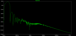
Out put FFT analysis.
Input 2Vpp,20KHz sin,4ohm load,
Distortion is -52db at 20KHz
and the component of distortion is dominantly 2nd harmonics
An externally hosted image should be here but it was not working when we last tested it.
The FFT is only for a rough reference due to the total distortion of my sig-gen directly coupling into my DSO is already around 58dB, see picture below。
An externally hosted image should be here but it was not working when we last tested it.
All test was down with JC2012 regulator PSU(the small board in the below picture)
An externally hosted image should be here but it was not working when we last tested it.
PSU temerature
An externally hosted image should be here but it was not working when we last tested it.
PSU temperature is 45c with amp work at full load for about 1hr.
An externally hosted image should be here but it was not working when we last tested it.
Test with real music
here are some test with real music
I used two piece of master works to test the amp. The above scope screen shot shows that the output wave form is the same as the input, except with much higher amplitude.
here are some test with real music
An externally hosted image should be here but it was not working when we last tested it.
An externally hosted image should be here but it was not working when we last tested it.
I used two piece of master works to test the amp. The above scope screen shot shows that the output wave form is the same as the input, except with much higher amplitude.
An externally hosted image should be here but it was not working when we last tested it.
An externally hosted image should be here but it was not working when we last tested it.
And the this amp is very stable with low resistance load. I tested with DC in 46.7V, output 80W into a 4ohm load. It worked at lease more than one hour and no thermal run-away. The total current stays stable at 2.1A.
- Status
- Not open for further replies.
- Home
- Amplifiers
- Solid State
- JC2012Doomday - The High Efficiency Version of JLH1969 Class-A