I just assembled the latest version(1.6) of the JC-2 clone, which I purchased from eBay seller Jim's Audio.
I checked everything carefully as I was assembling it.
When it came time to try it out, all I had was a Rat Shack 25.2V CT 2A transformer to test it with.
After connecting the transformer and plugging it in, the LED on the +Vcc side flickered briefly and remained unlit while the -Vcc LED remained lit.
The instructions state to adjust the 2K trimmers to obtain between 15 and 20 volts.
My problem is the trimmer adjusts the voltage on the -Vcc side, but when I turn the trimmer on the +Vcc side it does nothing. The voltage stays at 17.4 volts.
So I adjusted the -Vcc to 17.4 volts(LED went out) and made the other bias and dc offset adjustments.
Can someone familiar with this design please tell me what may be wrong?
I've looked at the schematic, but I don't understand the purpose of the (3) BD140 & (1) BD139 transistors unless they are part of some type of voltage regulator circuit.
Thank you...
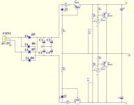
Looks like a shunt regulated supply. The first transistor and LED on each rail form a constant current supply of around 100+ milliamps give or take (the LED colour, and hence its forward volt drop determine the exact value). The LED creates a known volt drop and the base emitter junction of the transistor + its emitter resistor is placed across this. So 1.8 volts LED voltage minus 0.7 volts B-E junction drop gives 1.1 volts across the 10 ohm (which equates to 110 ma flowing). That current only flows when there is a load on the supply (the shunt regulators)
The second transistors and TL431 form what is really a high power zener stabilising the output at the preset value by causing the shunt transistors to conduct.
The second transistors and TL431 form what is really a high power zener stabilising the output at the preset value by causing the shunt transistors to conduct.
Ok, thank you for enlightening me on what the circuit is and how it works.
The LED's are 5mm and they're red. I don't know their voltage.
So are the LED's supposed to be lit all the time or lit under certain conditions?
With 12.6VAC going to each side, the heatsinks aren't warm at all.
Is 25.2 volts enough for this circuit to operate, or does it require more voltage?
As I stated above the negative rail's voltage is adjustable when turning the 2K trimmer, but the positive rail sits at the rectified voltage of 17.4 volts.
If you have full supply voltage of 17 or so volts at all times it means the positive regulator is non-functional. If the LED is not lit it could mean not enough voltage for the reference voltage is available.
Don't forget the likelihood of errors. If you are lucky, the parts that could have been faulty when fitted (unlikely) or fitted incorrectly (could be by an error or lack of clarity on the overlay even) will still be OK. Double check your parts orientation by veryfying that the component pins are indeed fitted as the marks indicate and that the PCB tracks are indeed oriented as the overlay and schematic seem to suggest. This is not a simple or quick check. Take your time and check thoroughly - yours and the manufacturer's possible errors, by confusing marks or substitute components that don't have similar pin orientation.
The quickest way to get correct pin I.D. is to simply Google part number + "pinout". Mind you use all numbers and letters in the actual part number, some TO92 transistors have had confusing differences. Make sure you have the correct orientation for the BD139/40 - easy to get wrong.
A first basic check for an operational circuit is to measure Vbe for each transitor. It will be close to 0.65V as measured from base to emitter at each transistor. Obviously, polarity will change for NPN or PNP types. Mooly has already detailed what the LED ref. voltage should be and it must be lit to provide that required stable voltage drop.
12VAC is not enough for a regulated 15-20 VDC supply. With a single transformer, as you find, it only outputs a raw 17VDC to each regulator and this could mean a significant ripple on the power rails, even at only 15VDC. You will need closer to 30V CT AC supply @ > 200mA rating to get proper low noise supplies and this design really does need very clean power.
BTW, whilst there will be some guys here who have built the preamp kit but likely the earlier type with linear regulation, you may get better understanding and response to your preamp kit problems in the "analog line level" forum where such kits are occasionally discussed.
Ian, thank you for all the info..
I will double check things like correct BD139/140 pin orientation and try a higher voltage transformer.
I initially tried a 30V CT transformer, that came out of an old Kenwood analog tuner, but I don't think it had sufficient current output since the voltage coming out of the transformer was pulled down to around 5 volts per side and the transformer became VERY warm after about 45 seconds.
Well, I have found the problems:
First, the transformer was voltage too low. I tried a 36 volt CT transformer which was really closer to 20 volts per side than 18 volts.
Next, I had the trimmer pot's screw, on the positive rail, turned in too far.
Backing it out several turns, along with using the higher voltage transformer, the LED illuminated on that side and the voltage is now adjustable.
Thank you again everyone for the help!
- Status
- Not open for further replies.
- Home
- Amplifiers
- Solid State
- JC-2 Clone +Vcc Problem...