Hey guys I need to recap my crossovers in my jbl sf25 quasi 3 ways
They are older versions apparently of the jrx125
I had an amplifier go bad and I suspect has damaged the caps in the crossover it did the same to another smaller set of speakers i thought i blew totally but the caps were destroyed
That made me realize the amp is a fault at my speakers expence unfortunately
and I'm having trouble findings the right value capacitor
Originally they are elytone non polarised 16uf and 12uf 200v
Does anyone know where I could get these ?
Or could some one please help provide a formuler to make some from other values keeping in mind the ripple current
The local electronic store has only limmeted value caps. I can do it from 100v bipolar caps but I believe they will not handle the power
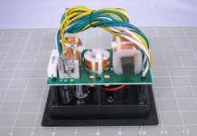
This looks like some sort of high efficiency 2.5 way speaker to me. Twin bass units and tweeter. 4 ohms nominal.
More tricky IMO, is you don't have much room for the typical axial non-polars that are freely available.
Electrolytic Capacitors
I'd think 100V types will be fine. Especially since it was a fault condition (DC offset?) that blew them, rather than merely loud usage.
12 and 16uF are common values here, but I'd be surprised if 10 and 15uF sound much different. You'd need a miracle to find radial types, which would make fitting easier, but look at some professional local PA suppliers.
Attachments
Hey guys thanks for the help you guys are great
After extencive searching for hours on different eBay sites I was able to find some polypropylene "mind my spelling". Capacitors that should be much much better quality than those electrolics they used and I've ordered them ,
I got some of the 100v bipolar caps from the store down the road for 16bucs and made them up and put them in
I figure I'd make sure it was definatly these caps that were the culprit with some cheaper ones first before I go waist more than twice that on expecive ones
And it fixed it
but just stressing over giving them full power cause I don't want to pop those little caps
All my bass was back and so much more punch " back to the way they should be "
Now they had a 16 ohm 10w. Resistor in em that coped some damage to , I replaced it with a 15ohm as that is only what the shop had.
No in regards to sound quality would I be best making a 10watt. Resistor out of 40x 1/4watt resistors
or just sourcing the new 16ohm 10w from mouser electronics as this is the only place I can source it
from
And would it be worth adding a small bypass cap say a .01uf to the others and the horn to clean them up a bit or improve the sound on top of the upgrades I have done
If needed I can open a new post about the resistor and bypass capacitor question to help other readers if needed
I don't know much about adding this little bypass cap as I have read about it on this forum Wilde trying to check and make sure the smaller voltage cap would be OK
Would I benefit from adding bypass caps and what size would I need ?
I can post crossover drawings and specs if needed
Cheers guys thank you
You might be moving into the "Snake Oil" category of the HiFi business here. 😉
The science says that even the worst wirewound RESISTORS have such tiny inductance relative to the drive units that you can ignore it. It's probably around 0.005mH, IIRC, which is an order of magnitude smaller than the lowest inductance tweeter.
Electrolytic capacitors have a significant resistance. It is perhaps 1 ohm for a 10uF capacitor. This means they do heat up with power. It also means the have a slight damping effect. Often this resistance is used to advantage in bass shunts to avoid a peakiness at crossover, but if there is a significant resistance (>2.2R) in the bass shunt anyway, you could probably ignore it.
You'd have to calculate the heating effect on a wirewound with the typical 30V peak to peak of most amps to determine if a resistor is going to get hot. Certainly temperature coefficients of resistance of wire say that something above 50 degrees centigrade rise is going to affect the real resistance. To confuse issues further, the voicecoil gets hot too and changes resistance. I don't know the figure as it goes, but I'd be more concerned if heating effects cause a fire under all that wadding when choosing 3W, 7W or 10W wirewounds. It's just how it works, but bass circuits dissipate far more real power than tweeter circuits. So I'd fit a 10W 2.2R in a bass circuit, and a 3W 2.2R in a tweeter circuit.
I'm not sure how seriously I take the whole polypropylene boutique CAPACITOR thing, but the current theory is that cheap 250V poly capacitors squeel around 14kHz. So if you want to bypass a 10uF tweeter capacitor with a smaller one, perhaps a very high quality 1uF would be a suitable value to try. Maybe 10% in other words. High quality usually implies a very high voltage rating (>400V) and thicker metal film. My own current notion is to fit the higher voltage types with thicker films to the bass circuit actually. High frequencies tend to find their way through tweeter circuits anyway. I could be wrong! 😱
Ferrite core bass INDUCTOR COILS are probably the most imperfect of crossover components, since ferrite is not very linear. On the other hand, drivers usually use ferrite magnets too, so you are only going to get half the improvement toward perfection by using air coils.
Long answer short? Beware replacing bass shunt electrolytics with polys unless you account for the resistance change which affect peakiness at crossover point (2dB?) and phase at crosover point (10 or 20 degrees) greatly.
Bypass with 10% of the original cap value using a higher quality unit. But, I really don't know if you'll hear it.
Tweeter circuits are not much affected by replacing non-polars with polys, but might sound
a tidge louder.
Don't get me onto CABLES, I just use decent 5A type stuff, but hard soldered is better than clip and crimp on connectors.
A very long post, sorry. 😀
Last edited:
In order to have a 16Ohm resistor, if you don't find the exact value, you could parallel 2x 33Ohm resistors for a net value of 16.5Ohm. In this case the power rating doubles (i.e, using 2x 5W resistor, you end up with a 10W equivalent resistor).
Ralf
Ralf
Cheers Ralph I know the calculations for running those parts in series and parralel if I can't get my hands on exact 16 ohm resistors I'll do like you said and join the two 5 watts then I'll have 15 and 16.5 ohm to see what the sound difference is I don't know if I'll hear it or not due to the fact that they have 10 percent tolerance and both are still within it ...
These resistors are the first thing the signal goes through and I'm sure do not run the highs I think it has something to do with the independence of the amp and amount of speakers connected
which is why it has to be 16 ohm using a 15 ohm resistor
my amp probly thinks its running a 3.7 ohm instead of 4 ohm speaker
The two 15 inch bass drivers "jbl mp115 8a"
in this setup are set up such so the bottom driver produces more bass and the driver above produces a little more mid hence the difference in the value of the two capacitors I need .....each one runs each bass driver the bottom would be at my guess 200hz and the top 500hz but don't quote me on them just a guess
They call it a quasi 3 way
The tweeter circuit does not run off the capacitors " I don't think " but runs off the two light globe style fuses that glow light a light bulb to absorb any overpower or DC so I shouldn't have any dramas with poly caps sqwealing there
The only other way I could possibly get close to these capacitor values is to take two polarised caps and join them to make a non polarized cap even then I wouldent get it exact
So I'm going to hope thee polys I bought are up to the task
As far as the inductors make an in perfect crossover argument I tend to agree I've been building for over ten years now and fortunately I'm Lucy enough to have moved into by amping and the use of electronic crossovers which I highly recomend it gives you the ability to tune any speaker and every song to its maximum potential but not every person has these or ends up going that way!
Plus I've seen lots of old speakers worth more than new cars still use hand wound inductor coils
The only difference in sound quality would be due to the silver content and quality
Unlike a lot of the Chinese stuff like these crossovers I'm reparing at the moment that jbl used in there lower end pa gear compaird to there vintage stuff like the L50 and L110's that I'm use to "I onlt lay like these quasi three ways cause I run them along side two jbl 2242 18inch bass brivers running at 90hz cause I like the feeling of everything viabriteing and the putty getting shook out the window frames
Now when dealing with bass and lower end frequency its harder to here the distortion most people can't pick it till it reaches 10% under 100hz
So I'm thinking any upgrade better than electrolic caps should produce far cleaner sound even if it not audible on the ears
But if you want quality and the best sounding speakers that are so sweet on your ears its like silk then you can't beat vintage jbl
replace/upgrade blown crossover capacitors jbl sf25 jbl2414h horn 2x jbl m115 8a dr
So really these bypass capacitors are just a way of trimming off the frequency by 10% either way! Would I be right
As far as the peakiness at crossover point 2db and the resistance change when using the polys are you refuring to the roll off?
I should be able to alter that by adding some resistors shouldn't I ?
Would you happen to have any reading material about this matter so I can learn some more about what you are telling me ?
Thanks so much 🙂
You might be moving into the "Snake Oil" category of the HiFi business here. 😉
The science says that even the worst wirewound RESISTORS have such tiny inductance relative to the drive units that you can ignore it. It's probably around 0.005mH, IIRC, which is an order of magnitude smaller than the lowest inductance tweeter.
Electrolytic capacitors have a significant resistance. It is perhaps 1 ohm for a 10uF capacitor. This means they do heat up with power. It also means the have a slight damping effect. Often this resistance is used to advantage in bass shunts to avoid a peakiness at crossover, but if there is a significant resistance (>2.2R) in the bass shunt anyway, you could probably ignore it.
You'd have to calculate the heating effect on a wirewound with the typical 30V peak to peak of most amps to determine if a resistor is going to get hot. Certainly temperature coefficients of resistance of wire say that something above 50 degrees centigrade rise is going to affect the real resistance. To confuse issues further, the voicecoil gets hot too and changes resistance. I don't know the figure as it goes, but I'd be more concerned if heating effects cause a fire under all that wadding when choosing 3W, 7W or 10W wirewounds. It's just how it works, but bass circuits dissipate far more real power than tweeter circuits. So I'd fit a 10W 2.2R in a bass circuit, and a 3W 2.2R in a tweeter circuit.
I'm not sure how seriously I take the whole polypropylene boutique CAPACITOR thing, but the current theory is that cheap 250V poly capacitors squeel around 14kHz. So if you want to bypass a 10uF tweeter capacitor with a smaller one, perhaps a very high quality 1uF would be a suitable value to try. Maybe 10% in other words. High quality usually implies a very high voltage rating (>400V) and thicker metal film. My own current notion is to fit the higher voltage types with thicker films to the bass circuit actually. High frequencies tend to find their way through tweeter circuits anyway. I could be wrong! 😱
Ferrite core bass INDUCTOR COILS are probably the most imperfect of crossover components, since ferrite is not very linear. On the other hand, drivers usually use ferrite magnets too, so you are only going to get half the improvement toward perfection by using air coils.
Long answer short? Beware replacing bass shunt electrolytics with polys unless you account for the resistance change which affect peakiness at crossover point (2dB?) and phase at crosover point (10 or 20 degrees) greatly.
Bypass with 10% of the original cap value using a higher quality unit. But, I really don't know if you'll hear it.
Tweeter circuits are not much affected by replacing non-polars with polys, but might sound
a tidge louder.
Don't get me onto CABLES, I just use decent 5A type stuff, but hard soldered is better than clip and crimp on connectors.
A very long post, sorry. 😀
So really these bypass capacitors are just a way of trimming off the frequency by 10% either way! Would I be right
As far as the peakiness at crossover point 2db and the resistance change when using the polys are you refuring to the roll off?
I should be able to alter that by adding some resistors shouldn't I ?
Would you happen to have any reading material about this matter so I can learn some more about what you are telling me ?
Thanks so much 🙂
Last edited:
So really these bypass capacitors are just a way of trimming off the frequency by 10% either way! Would I be right
As far as the peakiness at crossover point 2db and the resistance change when using the polys are you refuring to the roll off?
I should be able to alter that by adding some resistors shouldn't I ?
Would you happen to have any reading material about this matter so I can learn some more about what you are telling me ?
Thanks so much 🙂
Well, if you want to be prissy, you'd include the bypass in the overall value. To make a 10uF, you'd better use, say, a low quality 9uF paralleled with a very high quality 1uF.
This is applying the old radio technique of bypassing, which can be quite crucial in the Mega Hertz range. In radio circuits you often bypass a cheap mica with a tantalum type. This is because the series inductance ESL becomes important at VERY high frequencies.
Lynn Olson thinks that oxide layers might have something to do with capacitor sound: Building a Better Capacitor
It could be that capacitors are microphonic too.
Cables are discussed here: Speaker Wire
My own belief is that very exotic cables present significant inductance and capacitance to affect amplifier loading and hence frequency response. But wire is wire really.
OK guys I bought some mkp x2. 0.1uf caps 275v. And some 0.01uf 630ppolycapsto experament with on boththe woofer circuts and the highs and I'll post the results bear in mind thiis only Apply s to my ears,amp, processor and speakers , and preferences in sound I prefure
given what I'm working with how hard its been driven and age
as if it was a woman everyone has different likes and admires differences in sound the same way to taste ......
I'll still post the results I notice in change , that I notice
But all in all , I suspect these xovers have been driven to **** any how before I got them
So any inproovment I hope should be exceptable
I did say about 10% for the bypass value for a reason. 🙂
Let's say you had a reasonable 3.3uF capacitor as your simplistic 3kHz tweeter filter. It has "whatever it is" imperfections in its nature. ESL (Equivalent Series Inductance) and ESR (equivalent series resistance) would be the significant measureables.
ESR is perhaps an ohm with non-polars, but a 10% bypass isn't going to help there, because it kicks in much higher.
You are really only going to affect the ESL (inductance) with a 10% bypass capacitor.
A 0.1uF is really tiny compared to the sort of values we are dealing with in an audio crossover. 0.01uF practically negligeable. I can't think of any improvement they could bring to a bass or tweeter crossover except at radio frequencies.
I have to disappoint you by saying these tiny bypass caps are not going to do much. The only use I would have for a 0.1uF is in a 10kHz bass notch in series with a 47R across the bass coil.
FWIW, a well designed amplifier usually has a 8R resistor plus about 1uF Zobel at its output to maintain high frequency stability above 20kHz. So don't get your hopes up. But I do admire anyone who has a bash at fixing stuff, and I look forward to hearing how you get on. 😀
Just my inner obsessive really, but I looked up the typical value of the amplifier output Zobel on my transistor Rotel unit. My memory had failed me. It is a little 10R 1W metal oxide, and 0.1uF MKT film type.
Its function is to keep high frequency load impedance low where the unknown speaker and cable might be presenting something nearer 200 ohms at around supersonic 100kHz. It's designed to be inaudible for the most part, but prevents oscillation.
Nevertheless, it still looks like 0.1uF is not doing much in audio crossovers. 🙂
- Status
- Not open for further replies.
- Home
- Loudspeakers
- Multi-Way
- jbl sf25 re-cap crossover trouble finding corect values