hi guys, i am blown away by this forum, it is awesome for you to be sharing info and help the way you all do.
and that has prompted me to seeking advice on a jaycar response 2x150 car amplifier, it is my mates amp, and i said i would like to try and fix it for him. he said that it didnt work and he took it to the repair shop ages ago and cant remember how much it was to fix it
When i went to power it up, i got a big bang and it smelt burnt, even though i only plugged in the earth and b+. on opening the box after, i found the burnt smell was a cooked transistor P55NE06, however i think just replacing this one would be pointless.
from looking around this forum and others, it seems i should replace all 8 of these transistors with STP80NE06-10 and on the board is the spots for another 2, and i should fill these spots as well with the transistors and bits to make them work.
to my untrained eye, the rest of the board looks fine and unburnt.
i am a newbie to electronics, however i have built several electronics kits, and am a very competent motor mechanic. i have not got a scope, but i do have a dmm and solder irons big and small.
what else can i look at to see if it is worth throwing money at to fix?
what else do i need to do, for you guys to help me fix it?
is it likely that replacing the trannys will fix it?
regards jack
Please post a photo of the amp board.
i am a week away from home, i will take a pic then, cheers
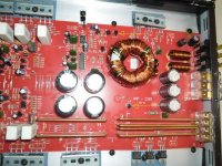
Hi all, attached are the board pics.
View attachment 251829
If we look at the unclamped P55NE at Q14, we can see that it is cooked, also Q12 looks only slightly better.
Please note that when i join my multimeter leads together on the 200ohm scale i get a reading of 0.2ohm.
When I put my multimeter on B+ and Earth i get 0.7 ohm (200ohm scale).
When I test the unclamped P55NE at Q12, Q14 and Q16, I get:
leg 1-3: 0.8ohm on 200ohm scale
leg 1-2: 0.3ohm on 200ohm scale
leg 2-3: 0.7ohm on 200ohm scale
When I test at the clamped P55NE at Q11, Q13 and Q17, I get
leg 1-3: 0.263ohm on 2k scale
leg 1-2: 0.264ohm on 2k scale
leg 2-3: 0.7ohm on 200ohm scale
From reading other topics it seems i should be replacing all 6 of P55NE. They seem a little hard to find although STP55NF06 are plentiful.
Are the STP55NF06 suitable replacement for the STP55NE06, or are there better choice (maybe STP80NE06)?
View attachment p55ne,p55nf,p80ne.zip
Should I install extra transisters and gate resistors and links at the blank places near Q15 and Q16?
View attachment 251830
If we look at the second attached picture, we can see some board discolouration near R401, it easier to see on the photo than real life. It seems to be from ZX1 which is right next to RX8, I think this might be a Zener Diode.
Do I simply replace ZX1 or does something else cause this to blow?
Regards Jack
Neither of your attatchments are viewable. What file format are you trying to upload them in? It says it is an invalid link. Are you uploading them with the manage attatchments option in the post? Its down below the text box a little ways.
Attachment were too big, sorry.
Hi all, attached are the board pics.

If we look at the unclamped P55NE at Q14, we can see that it is cooked, also Q12 looks only slightly better.
Please note that when i join my multimeter leads together on the 200ohm scale i get a reading of 0.2ohm.
When I put my multimeter on B+ and Earth i get 0.7 ohm (200ohm scale).
When I test the unclamped P55NE at Q12, Q14 and Q16, I get:
leg 1-3: 0.8ohm on 200ohm scale
leg 1-2: 0.3ohm on 200ohm scale
leg 2-3: 0.7ohm on 200ohm scale
When I test at the clamped P55NE at Q11, Q13 and Q17, I get
leg 1-3: 0.263ohm on 2k scale
leg 1-2: 0.264ohm on 2k scale
leg 2-3: 0.7ohm on 200ohm scale
From reading other topics it seems i should be replacing all 6 of P55NE. They seem a little hard to find although STP55NF06 are plentiful.
Are the STP55NF06 suitable replacement for the STP55NE06, or are there better choice (maybe STP80NE06)?
View attachment p55ne,p55nf,p80ne.zip
Should I install extra transisters and gate resistors and links at the blank places near Q15 and Q16?
Hi all, attached are the board pics.
If we look at the unclamped P55NE at Q14, we can see that it is cooked, also Q12 looks only slightly better.
Please note that when i join my multimeter leads together on the 200ohm scale i get a reading of 0.2ohm.
When I put my multimeter on B+ and Earth i get 0.7 ohm (200ohm scale).
When I test the unclamped P55NE at Q12, Q14 and Q16, I get:
leg 1-3: 0.8ohm on 200ohm scale
leg 1-2: 0.3ohm on 200ohm scale
leg 2-3: 0.7ohm on 200ohm scale
When I test at the clamped P55NE at Q11, Q13 and Q17, I get
leg 1-3: 0.263ohm on 2k scale
leg 1-2: 0.264ohm on 2k scale
leg 2-3: 0.7ohm on 200ohm scale
From reading other topics it seems i should be replacing all 6 of P55NE. They seem a little hard to find although STP55NF06 are plentiful.
Are the STP55NF06 suitable replacement for the STP55NE06, or are there better choice (maybe STP80NE06)?
View attachment p55ne,p55nf,p80ne.zip
Should I install extra transisters and gate resistors and links at the blank places near Q15 and Q16?
If we look at this second attached picture, we can see some board discolouration near R401, it easier to see on the photo than real life. It seems to be from ZX1 which is right next to RX8, I think this might be a Zener Diode.
Do I simply replace ZX1 or does something else cause this to blow?

Regards Jack
Do I simply replace ZX1 or does something else cause this to blow?
Regards Jack
The board is discolored due to heat stress. This is common on amps that use such simple voltage regulators but the Zener diode (at the end of the resistor) should be checked. Sometimes a defective zener can cause greater heating than there should be.
What is the value of the gate resistors for the power supply FETs?
What is the value of the gate resistors for the power supply FETs?
Thank you for your prompt reply.

All the resistors at R35, R37 and R41 measure at:
R35: 14.5
R37: 14.5
R41: 14.5
All 200 ohm scale.

However the resistors on the other side measure:
R36: 46.1
R38: 46.1
R42: 46.1
All 200ohm scale.
I am pretty sure these are the gate resistors.
The resistor colours are Yellow, Blue, Black, Gold.
All the resistors at R35, R37 and R41 measure at:
R35: 14.5
R37: 14.5
R41: 14.5
All 200 ohm scale.
However the resistors on the other side measure:
R36: 46.1
R38: 46.1
R42: 46.1
All 200ohm scale.
I am pretty sure these are the gate resistors.
The resistor colours are Yellow, Blue, Black, Gold.
They are 47 ohm resistors. You can use a wide range of FETs in the amp. I suggest using the originals but if they're not available, you can use IRFZ44s, IRFZ46s, IRFZ48s IRF3205s would probably also work.
You need to check the PNP transistors that are driving the FETs as well as each of the individual gate resistors.
You also need to check the output transistors to confirm that none have failed.
You need to check the PNP transistors that are driving the FETs as well as each of the individual gate resistors.
You also need to check the output transistors to confirm that none have failed.
Thanks Perry,
I have ordered 10 of the IRFZ44. Should I install only 6 of them or fill the other spaces at Q15 and Q16 (visible in post #9) and use 8?
I am not sure where the PNP transistors that are driving the FETs are, but the excellent Basic Amplifier Repair page suggests they are quite small. I only have 6 small Transisters on the power side, so i will look at them.
WRXR,
While it may be tempting to put 8 PS fets in (as a likely upgrade for the original 6) keep in mind that there may be other aspects here where just adding more wouldnt help much, like using IRFZ48 instead of IRFZ44 would in iteself be enough upgrade using 6 components. Enough upgrade is likely not measurable and insignificant. I've seen a few amps with provision for extra transistors and have always been tempted myself.
Also keep in mind that you will have to drill and tap extra holes in the sync, plus source lengthier stock squishing the new transitors firmly. Not to mention the torroid in fact may not even be capable of more power. If it were my amp and I desired to upgrade, I'd probably look at 6x IRFZ48 - my opinion.
Thank you for your prompt reply.
View attachment 251896
All the resistors at R35, R37 and R41 measure at:
R35: 14.5
R37: 14.5
R41: 14.5
All 200 ohm scale.
View attachment 251896
I have desoldered the transistors at Q12, Q14 and Q18.
I have desoldered one end of the gate resistors. Now they read-
R35: 45.9
R37: 45.9
R41: 46.1
All 200 ohm scale.
Do we think the R35 and R37 should be replaced?
The emitter of the driver transistors connects directly to the gate resistors. One driver goes to 3 of the FETs. The other driver goes to the other 3 FETs. I would suspect that it's the two indicated by the arrows in the attached photo.
Thanks,
I have removed the board, turned it over, traced the tracks and, as you suspect these are the driver transistors. Using the multimeter in the 200 ohm scale, there are no shorts in these 2 transistors.
Output Transistors

I presume these are the output transistors, the transistors on the opposite side of the board test fine, however these transistors are not so good.
I removed there 4 transistors and checked them individually. Q112 and Q115 were fine, and i have replaced them. Q113 and Q114 have shorts. I will get a TIP36C and TIP35C to replace them.
I detect a pattern, so i have compared the gate resistors at R100, R167, R168 and R175 with the resistors on the other side of the board and they are comparable.
Where do I need to look now?
These are not gate resistors at R100, R167, R168 and R175.
Gate resistors are at at R178 and 7 other places. They all have 4.9 on 200 ohm scale.
Driver transistors for the outputs are at Q109 and 3 other places. They have no internal shorts
Gate resistors are at at R178 and 7 other places. They all have 4.9 on 200 ohm scale.
Driver transistors for the outputs are at Q109 and 3 other places. They have no internal shorts
Check also drivers for defective output transistors, Q100 is one of them.
Amp looks very much like Renegade REN1000s I have had 3 of them with blown outputs and 2 of them had also blown drivers.
Amp looks very much like Renegade REN1000s I have had 3 of them with blown outputs and 2 of them had also blown drivers.
Yes, thanks Mote. I think its Q109 not Q100 (bit hard to pick it in the photo). But I checked them. There is 4 of them and they each drive into 2 gate resistors and in turn into a TIP35C and TIP36C.
I think they are the ones you are talking about.
If so, they checked ok
I went down the local shop and got a TIP35C and a TIP36C and some 47ohm resistors.
The TIPs are enclosed (T-220?). I think its OK to just replace the 2 of these as required at Q113 and Q114, or should all of them be replaced?
The 47 ohm resistors are the gate resistors for the FETs, they only had them in 47ohm 1%, so i have replaced all 6 of the gate resistors at R35, R36, R37, R38, R41 and R42.
What needs to be checked here as it looks a little burnt. Hard to see but ZX1 may be cooked, what is it and how do i check it

I have looked at QX1 and it has no shorts.
I think they are the ones you are talking about.
If so, they checked ok
I went down the local shop and got a TIP35C and a TIP36C and some 47ohm resistors.
The TIPs are enclosed (T-220?). I think its OK to just replace the 2 of these as required at Q113 and Q114, or should all of them be replaced?
The 47 ohm resistors are the gate resistors for the FETs, they only had them in 47ohm 1%, so i have replaced all 6 of the gate resistors at R35, R36, R37, R38, R41 and R42.
What needs to be checked here as it looks a little burnt. Hard to see but ZX1 may be cooked, what is it and how do i check it
I have looked at QX1 and it has no shorts.
#14:
The resistors are OK. They are 5% tolerance components so they are within tolerance.
#15:
You have to confirm that both drivers have no leakage and that each one has two good junctions. If you don't understand what this means, read the 'checking bipolar transistors' on the basic repair page and follow the link to the 'checking semiconductors' page.
#16:
You must replace all 4 of the output transistors if you want the amp to be reliable.
These transistors are BJTs, not FETs. BJTs have a base, not a gate so the resistor connected to the base would be a base resistor.
#19:
The TO-220 case is the smaller case, like that used by the poser supply FETs. Are they fully encapsulated or do they have the metal tab exposed on the rear of the transistor?
When checking the diodes out of the circuit with the meter set to diode-check, you should read approximately 0.7v one way and OL with the probes reversed.
- Status
- Not open for further replies.
- Home
- General Interest
- Car Audio
- jaycar response 2x150 blown