Hi,
first question - first post - absolute beginner in all respects.
I have a SC-480 power supply kit.
It provides regulated +/-40volt supply for the amp module and an option for +/- 15 volts for ancillary equipment.
I am going to use it on a SC-480 amp module.
I will be getting a toroidal tranformer +/-30 volts with auxillary windings of +/-12 and +/-15 volts - cannot get a +/- 28 volts as suggested.
I need +/- 20 volts. Can I safely exchange the zener diodes to say 20 volt instead of the 15 supplied and up rate the caps to 100uF 25 volt instead of the 100uF 16 volts supplied? any other changes needed? I assume the resistors used are only to limit the current and nothing else?
Why? - I have an old 70's SQ decoder and rear amps that I wish to make better and modernise the power supply and amp section. Do not want to change to much. The 20 volts is required for the SQ decoder section.
Next I need 6 volts from somewhere to run some lights on the amp.
Suggestions advise really welcome.
Cheers
Bill
Bill,
30+30VAC torroid will be fine for the main outputs. Using a toroid is better than the typical EI core transformers that JAYCAR and co sell as 28+28VAC transformers.
For the +/-20VDC outputs you might want to be a little more cautious. the answer is however a qualified "Yes" but go in with your eyes open.
Trying to be helpful, here are some tips on what to watch for.
-1- Measure the current the decoder draws. Do this my putting an ammeter in series witht he supply in it's current installation. You need to do this to understand how much current the DC supply needs to deliver.
-2- Given the above, if it is not a crazy amount (without being precise, I would say 50mA will be pretty do-able - but read on) then you can probably use the Zener / Resistor setup.
-3- The resistor in the Zener / Resistor setup is there to drop the voltage from the main supply voltage to the regulated rail voltage. What the hell is this saying???
Say the main supply rail comes out to 42VDC, then the resistor is dropping (42 minus 20) volts, or 22 volts.
So what?
The current through this resistor is the sum of -a- the decoder, and -b- a standing current through the Zener. Typically needs to be > 10-20mA. So in this case, it would be 50+20 mA.
So the resistor need to drop 22Volts when carrying 70mA. This is a 314Ohm (or 330 in anybody sensible's) books - which will need to be 2-3 watts (I would go 5W).
You will need to do some of you own measurements and sums to get this right - and do NOT assume that the example above uses the values in your circuit.
Alternatively, you could build a nice voltage regulator circuit - Jaycar, Altronics and DSE all stock them. Your only question then would be how big a heatsink you need🙂
And yes, simply up the voltage ratings of the caps.
Last edited:
Cheers googly one.
What you describe, I can understand - that jogged some old grey matter.
Please bare with me here.
So the voltage I need is also dependent on the resistors.
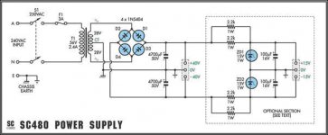
The original uses 2 x 2.2kΩ 1W 5% resistors in parallel - equivalent to a 1.1k ohm? per side. I've also attached the circuit. I hope I read it well - extracting long dormant information from old grey matter.
Yup I'm with you. so for the original.
So v=ir, we want to get 42 volts to 15 volts , so we would need to drop 42-15=27 volts across the resistor - so we would have 27/1100 = 24mA.
So reversing that 22/24mA would give me 900 ohms = 2 x 1800 in parallel to suit the circuit - both sides for the +/- 20 volts.
That is 42 volts - 22 to get 20 volts.
Or I'm lost and just confused the issue here?
What you describe, I can understand - that jogged some old grey matter.
Please bare with me here.
So the voltage I need is also dependent on the resistors.
The original uses 2 x 2.2kΩ 1W 5% resistors in parallel - equivalent to a 1.1k ohm? per side. I've also attached the circuit. I hope I read it well - extracting long dormant information from old grey matter.
Yup I'm with you. so for the original.
So v=ir, we want to get 42 volts to 15 volts , so we would need to drop 42-15=27 volts across the resistor - so we would have 27/1100 = 24mA.
So reversing that 22/24mA would give me 900 ohms = 2 x 1800 in parallel to suit the circuit - both sides for the +/- 20 volts.
That is 42 volts - 22 to get 20 volts.
Or I'm lost and just confused the issue here?
Attachments
And if I choose the right resistors I can limit the current?
If I say allow 150ma.
I would need 22/0.015 = 1466 or 2x 2.7kohm in parallel? or 2 x 3.3kohm? both sides.
If I say allow 150ma.
I would need 22/0.015 = 1466 or 2x 2.7kohm in parallel? or 2 x 3.3kohm? both sides.
And I find the decoder requires 75mA and 20 volts.
Found specs on the net.
So we would have 22/0.095 (allowing 75 +20) = 231 ohms so 2 x 470 ohm in parallel per circuit.
so current would be IxIxR = 4 watts
Yup 5 watt 470 ohm.
???????????????????????????????????????????????????????????
Found specs on the net.
So we would have 22/0.095 (allowing 75 +20) = 231 ohms so 2 x 470 ohm in parallel per circuit.
so current would be IxIxR = 4 watts
Yup 5 watt 470 ohm.
???????????????????????????????????????????????????????????
Yep, you have got the theory.
The practise of this is:
-1- 4 Watts = HOT
-2- If you have your decoder in circuit, the 75mA it uses goes through the decoder - which is just fine, leaving 20mA flowing through the diode.
The diode dissipation is then 0.02*20 = 0.4 Watts. Use a 1W zener and when you mount it, leave a good 10mm between it and the board (i.e. leave it standing proud of the PCB).
-3- If you do not have the decoder connected, then you have both the 75mA and the 20mA going through the zener diode. Which is 1.8Watts, which is again HOT. Most Zeners will get pretty upset at this!
So the advice here is to be careful about this configuration. This is partly why zener regulators are not wildly popular.
Mitigations to this risk are:
- Masure the currents the decoder uses on each rail (as disucssed)
- Set the resistors appropriately (as discussed)
- Be conscious of the issues that heat may create
- Look at the exception cases - eg "what if I don't connect the decoder"
- Build it and check how it goes. Check for things getting stinking hot.
I still suggest that you consider the option of a seperate +/-20V IC regulator circuit - check the JAYCAR catalogue, they have a simple PCB you can choose your output voltage on. This is much more tolerant of the issues identified above.
Hi,
The decoder will always be in circuit as it is always on.
I say that with reservation as there is a facility of switching from mono stereo enhanced and quadraphonic. With the mono and stereo the rear amp section is disconnected and the signal is in and straight back out to the front main amp - so at that stage the decoder may well be out of circuit but always connected to the supply voltage.
A separate IC circuit may well be the go.
I figure the one rail will get hot if I stay with the option of using the zener regulator as it will be running the one side - the other side will be the negative rail with respect to the ground.
Cheers my friend.
best regards
bill
Hi again,
Jaycar do a power supply KC5501 which is +/- 15 volt dependent on the regulator used.
I will assume that the kit has a 15 volt regulator as standard. It says other voltages are available by using the 78xx regulators. That being so, could I replace the regulators with a 24 volt one as I could supply the AC from one of the 15 volt auxillary windings from the toroidal?
Would that be OK as the other option is the 1.25 - 22 volt regulator but that would require at least a 22 volt supply anyway.
Thanks for bearing with me on this.
Best regards
Bill
- Status
- Not open for further replies.
- Home
- Amplifiers
- Power Supplies
- Jaycar Altronics SC-480 Power Supply