CFP output stage
Hi ATAUDIO,
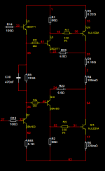
In the past i have done several compound outputstages (CFP) and i have ended up with the attached schematic.
Idling current is more stable because of R3 and R4, the thermal stability is increased but you will lose some headroom.
To minimise crossconduction set the value of R1 and R2 to a value as low as 49 Ohms. I choose 68 Ohm.
best regards,
Piersma
Hi ATAUDIO,
In the past i have done several compound outputstages (CFP) and i have ended up with the attached schematic.
Idling current is more stable because of R3 and R4, the thermal stability is increased but you will lose some headroom.
To minimise crossconduction set the value of R1 and R2 to a value as low as 49 Ohms. I choose 68 Ohm.
best regards,
Piersma
Attachments
Intersting...Hi ATAUDIO,
In the past i have done several compound outputstages (CFP) and i have ended up with the attached schematic.
Idling current is more stable because of R3 and R4, the thermal stability is increased but you will lose some headroom.
To minimise crossconduction set the value of R1 and R2 to a value as low as 49 Ohms. I choose 68 Ohm.
best regards,
Piersma
How you choose R20 and R23?
Did you want to have some voltage gain or are them there only to reinforce degeneration on driver side?
All the rest is pretty standard.
Thanks a lot
thanks for your kind words ataudio
i am sorry to say that i never had the schematic of the specific amp ... stil though i own 4 of these speakers and a spare board ... between me and you it could be much easier to sent you a spare part than trying to hand draw a schematic ..too bussy to do that .
there is no chance ( from time aspect ) that i can do the schematic for you now ... may be after the sumer ..though this is a very ineteresting thread and i will stay tuned .
some information may be found around an amplifier that as presented somewhere here called Joy 200 .. i think alexmm made pcb for it
( by the way should we call the alex mm the absolute pcb designer for the solid state forum (eventhough i dont like none of the pcb he makes) .... too square and all under the same patern .... )
i think that there is already some people that builted the amplifier so may some aditional feedback may flow for this one also ...
for the record and next to your amplifier and the joy 200 i havent meet with any other comercially made sziklai with multiple outs .... may be less than a handfull .... probably cause its not easy to stabilize ...
keep up the good work and lets see how it comes up
Yes, driving a CFP from an emitter follower is a good idea as CFP has a very non-linear input impedance. A typical VAS with Miller compensation is a current source at low frequencies so a CFP would give serious LF crossover distortion which the global NFB then has to correct.
You forgot the Nakamiki PA7, Sakis.ifor the record and next to your amplifier and the joy 200 i havent meet with any other comercially made sziklai with multiple outs .... may be less than a handfull .... probably cause its not easy to stabilize ...
keep up the good work and lets see how it comes up
And there are also Crown, but they are CFP triples, and that is another story.
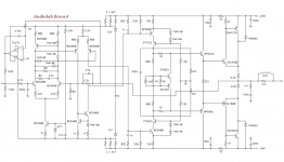
I see that TPC is referred to ground. I have always seen it to a rail (i.e the Self's Blameless). Is that correct?Here is an updated schematics, taking in account to various suggestions.
Special thanks to OS, who made most of them.
Which is better, CFP or Darlington ? I've heard ppl have oscillation problems with this Sziklai topology.
For the signal, it should not make any difference, but since we have here a CLEAN ground...I see that TPC is referred to ground. I have always seen it to a rail (i.e the Self's Blameless). Is that correct?
I belive this is a fruitless question, posed so many times and in so general terms. If you want to pursue it, I strongly invite you to open your own thread, whre I will happily post. Thank you.Which is better, CFP or Darlington ? I've heard ppl have oscillation problems with this Sziklai topology.
BTW, I am on a trip abroad for a while, so I will not follow the thread daily. But be assured, the project, for the few that might be interested, is going on.
Last edited:
Member
Joined 2009
Paid Member
BTW, I am on a trip abroad for a while, so I will not follow the thread daily. But be assured, the project, for the few that might be interested, is going on.
It's been a long trip 😀
- Status
- Not open for further replies.
- Home
- Amplifiers
- Solid State
- JAS - Just Another Sziklai