Sorry my posts appear out of sync with everyone else- I am still under moderation, which is getting slightly annoying - however-
In papers put before the AES, (notably by luminaries such as Karten Nielson of Ice power fame in Munich 1997) natural sampling is defined as a PWM modulator which has a fixed reference, triangle or ramp to derive the pwm signal.
Phase shift modulation is where you have two square waves, and the audio is carried on the phase difference between the waves, so
when you have 0 output, both square waves superimpose on each other so the net voltage across the bridge is also 0V, when the signal goes positive, one square wave MS ration increases, the other decreases, this gives two positive pulses, the inverse is correct for negative signal, the first square wave ms ration decreases, the inverse wave increases, giving two net negative pulses.
the first thing that should jump out is you have without increasing the sample rate, doubled the apparent sampling rate!
This 3 level pwm has great efficiency benifits at low powers, my area of need, and with good inductor choice sounds good too!, the emc filtering is also predictable- so limited RF crud (as long as fet snubbing etc. is controlled).
In another thread I am interested in persuing the idea of a self oscillating phase shift amplifier- maybe this is of commercial benifit to either coldamp or hypex? I am personally interested in the technology of the thing.
regards
Chris-
The type of modulator I use has a much better idle condition than at 90% modulation index, the only error being the winding difference on the common mode choke following the output stage and small variations in filter component tolerances.
Bruno-
My products do drive cables over 500m so to me it is important, for HiFI and using a single ended drive, I fail to see the use of a common mode choke in suppression, the signal is not differential and transimitted common mode, but sent out on one conductor and returned on the other the same as the audio; if a common mode choke would remove the HF then it would also remove the audio by definition.
Thanks, Bruno for putting all that things into a single post for clarification.
From my experience, I agree with Bruno in almost everything he has stated. Specially in that EMI behaviour has little to do with modulation scheme, provided that the switching residue has been attenuated enough.
I hope that, from my words, no one thinks that carrier-based Class-D amps are intrinsically superior to Self-Oscillating ones in the EMI matter. The possible advantages come from the way filtering can be done due to the fact that switching frequency is estable (tuned notchs, for example), but a self-osc. amplifier doesn't radiate more only because it is self-oscillating, that's a myth.
Best regards,
Sergio
Three-level PWM is something of an open-and shut case.
Suppose you use 2x150kHz to get the same sampling rate as 300kHz. Fine, that works great. Now, how do you filter this thing?
Option 1: A differential mode filter followed by a common-mode filter. In terms of ferrite volume, this is the most optimum. Unfortunately, as there is no differential mode carrier, there is also no differential mode ripple current going through the coils and the power stages. When you're designing for low power, this current is of paramount importance to get zero-voltage switching. In two-state amps, the filter helps recover the energy stored in the snubbers and Cout of the FETs during the dead time. Out the window goes the low-power advantage. In addition, the lack of ZVS means that the output stage becomes exceedingly non-linear at the zero crossing unless the dead time is made zero! The increase in distortion greatly outweighs the improvement to be had from the doubling of the sampling rate. Out the window goes the performance advantage.
Option 2: Two single-ended LC filters. The amplifier now operates as two separate half-bridge amps. This is less efficient in terms of ferrite. Worse still, because one was hoping to run the amps at half the switching rate as before, the current in the coil becomes hopelessly high unless it too is doubled in inductance. If the total ferrite volume of a 2x150kHz amp is kept the same as that of a 1x300kHz amp, the core losses will be up to 8 times higher. Out the window etc... If the total ferrite volume is increased to get the core losses back to normal, the filter size has increased substantially.
Option 0: No filter. This is the only application where 3-level has any merit. You can't omit the filter in a 2-level amp because that would produce unacceptable losses in the speaker. In a 3-level system you can get away with it. The distortion problem of option 1 remains and the RF performance (which is the start of this discussion) is hopeless. The efficiency is not very good, but the scheme is used for ultra-low cost low-power systems.
Apart from that, I'd like to note that if you want to take advantage of the sampling rate doubling, you need to use one control loop sensing both outputs. Because there will be no differential-mode residual in the loop, you cannot use it in a self-oscillating setting. Only a clocked system will do. Now, as anyone knows, a clocked system has much lower loop gain than a self-oscillating system so there goes the advantage of frequency doubling.
As you can see, these are all very practical issues which, apart from the last point, cannot be discovered by armchair theorists churning out large amounts of maths.
Anthony C Smith said:I fail to see the use of a common mode choke in suppression, the signal is not differential and transimitted common mode, but sent out on one conductor and returned on the other the same as the audio; if a common mode choke would remove the HF then it would also remove the audio by definition.
The HF that we care about is the one that radiates from a cable, and that is the common mode. This is removed by the common mode choke. The HF that is NOT removed by a common mode choke is the differential mode, but that's the HF that we DON'T care about, because the speaker doesn't care for it.
Bruno,
I agree with most of what you said about 3 state PWM, however there are big differences between the RF problems of a TI 3state vs a 3 state where the subtraction is done before the HBridge. In the later case you have a minimum pulse problem and a deadband problem to overcome however you get reduced RF.
The big problem, as you rightly point out, is that low distortion is only achieved when the minimum pulse width and minimum deadband are close to zero. (think 1-2nsec maximum deadband)
Typically this minimum pulse / deadband problem shows up as very poor performance for -60dB Audio inputs. (SNR 20dB or less)
The only way around this problem is to dither the system, which unless you are very careful, results in the dither components folding down into the audio band.
You can always segment the FET's to achieve the desired Rise / Fall times but this introduces the problem of non-constant RDSon, which translates into a gain error at small signals, fortunately this error is easy to predict and pre-compensate.
If the truth is told all this is done to save a few pennies on filter components not for better audio or lower RF.
I still think there is a good case that can be made for using 3 state and 4 state PWM systems BUT it is not an area for the hobby community.
Simply put (3 state PWM) too many problems and too few benefits!
Classdunce
I suppose you are referring to Apogee DDX there. As far as the carrier-frequency component is concerned, this is correct, and counts as pretty much the only advantage to DDX. However, since filterless designs are intended to go into the same box as the speaker, the carrier frequency is too low to be going anywhere. The higher harmonics on the other hand are not as much determined by the modulation method as by the dV/dt of the power stage (and ringing and so on).ClassDunce said:there are big differences between the RF problems of a TI 3state vs a 3 state where the subtraction is done before the HBridge. In the later case you have a minimum pulse problem and a deadband problem to overcome however you get reduced RF.
Bruno
I was thinking Apogee and that Korean ClassD, can't think of the name of it plus a couple of recent Tiawan attempts
BTW I posted a question on another thread that I hoped you might address, simply put the question is,
Why isnt the carrier FM of a self oscillating amp audible?
I read a where you were talking about the PDF of the modulator and all that, which is interesting BUT if you put a spectrum analyzer on the carrier you see massive audio side bands with clear FM and AM components. This has to fold down given even a moderate non-linearity in the output or filter.
Classdunce
Bruno-
Firstly I am no armchair theorist, and my experience comes from delivering emc compliant product to my customers- the tone in your post is dismissive and insulting.
I did not mention the items about tweeter frying etc. which are purely bunkum- however
my question which i presume has been passed from Jan peter to you was about en55103 classification-
a revision of 55103 is underway and many changes are in order to address the way "self oscillating designs" are tested this may prove of value to you, ISCE have been asked to comment on these proposals- a good reason to join for some, and I hope people who are informed like yourself will join us.
neither you or JP have answered this, please do so-
BTW- I didnot propose 3 level pwm as an answer, it does have major flaws as you point out, notably dead time, but with good design you can still achieve 0.01% thd- (better than most real high street HIFI anyway) my original post was about realising a new design on the basis of self modulation, as this still appears to have advantages, and I have not examined this form of oscillation for many years- 3 level NSPWM has provided me with a saleable product for my corporate head, and a reasonable home sound, this year I have less of a work load and wish to personally examine a different way forward, Async PWM or a bridge version of Async PWM looks promising, who knows but at least I believe I have the ears and the industry tools to evaluate them( not just a radio and a multimeter), and I am not coldly dismissive of people who do not agree with me.
yours truly
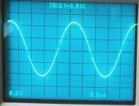
Now that the issue has been discussed today:
This is a question for Bruno or J-P:
Is this a good output waveform in terms of EMI/RFI, or does it have excessive ripple / ringing?
It shows around 320mV rms output ripple and around 200mVpp ringing at the switching events.
This is a question for Bruno or J-P:
Is this a good output waveform in terms of EMI/RFI, or does it have excessive ripple / ringing?
It shows around 320mV rms output ripple and around 200mVpp ringing at the switching events.
Attachments
I have just read the post regarding the CM filter, sure it attenuates the E field, but its a closed magnetic loop and this is radiated as a H field, and is easilly received by an am receiver, try tests in an open area space and not a tem cell, then comment.
regards
regards
Unfortunately Pierre I cannot see the peaks of the switching waveform, what is the bandwidth of the scope used?, and is it possible to repeat with a longer shutter time, and higher contrast so the spike come into view?? or do they not exist and i have mis read your post?
regards
regards
I wasn't talking about you, I was talking of the "luminaries" who sang the siren song for 3-level modulation without considering the effects on the power stage. I'm sorry that wasn't obvious - I'm not the kind of chap who goes insulting his interlocutors. I apologise if it came across that way.Anthony C Smith said:Firstly I am no armchair theorist, and my experience comes from delivering emc compliant product to my customers- the tone in your post is dismissive and insulting.
The thread in general is about "is xxx mV of residual OK". I was answering that one, not specific posts in particular.Anthony C Smith said:I did not mention the items about tweeter frying etc. which are purely bunkum-
I am certainly interested in joining.Anthony C Smith said:my question which i presume has been passed from Jan peter to you was about en55103 classification-
a revision of 55103 is underway and many changes are in order to address the way "self oscillating designs" are tested this may prove of value to you, ISCE have been asked to comment on these proposals- a good reason to join for some, and I hope people who are informed like yourself will join us.
neither you or JP have answered this, please do so-
I realise that. I discussed 3-level PWM because it was brought up, not because it was proposed as a solution. Otherwise I'd have simply said that for common mode AD is best, for differential mode BD is best.Anthony C Smith said:BTW- I didnot propose 3 level pwm as an answer
So far it seems difficult make a self-oscillating modulator in "true" BD mode ie. with retention of the double-sampling advantage, because self-oscillating schemes rely on the residual (which, unfortunately, is cancelled in BD). Bridging 2 UcD amps with an additional cap across the load does result in effective BD mode, but the loop bandwidth remains unchanged with respect to just one half.Anthony C Smith said:Async PWM or a bridge version of Async PWM looks promising, who knows
This is not to say it can't be done. Your best shot would probably be to look into hysteresis type modulators, using the hysteresis as a separate degree-of-freedom to set the phase relationship.
Again sorry for upsetting you. It was unintended and unexpected.
Cheers,
Bruno
Pierre said:Now that the issue has been discussed today:
This is a question for Bruno or J-P:
Is this a good output waveform in terms of EMI/RFI, or does it have excessive ripple / ringing?
It shows around 320mV rms output ripple and around 200mVpp ringing at the switching events.
In my book it looks like "just OK". It's quite similar to what we see in the UcD180. The 400 and 700 are quite a bit better in that respect, owing to the better inductor (more expensive alas).
Anthony C Smith said:I have just read the post regarding the CM filter, sure it attenuates the E field, but its a closed magnetic loop and this is radiated as a H field, and is easilly received by an am receiver, try tests in an open area space and not a tem cell, then comment.
regards
The CM choke is by far not a surefire solution. Another way to reduce its effectiveness is having asymmetrical capacitance to ground - not unlikely in long cable runs.
We do have a true solution to the problem though, but the product is still under development.
Bruno Putzeys said:
In my book it looks like "just OK". It's quite similar to what we see in the UcD180. The 400 and 700 are quite a bit better in that respect, owing to the better inductor (more expensive alas).
Good answer, kind of, because to me it looks strikingly familiar to something Sander posted as being the output of his UCD400 based amp.
Bruno- I am sorry for "taking the Hump" as we call it.
As for the ISCE we would welcome you, and a great many others in this forum, although we are UK based we have members all over the globe, we have input to cenelec and BSI on standards which effect our market, we hope we provide an independant voice unlike coporate Europe who just want exclusiveness.
for my sins I sit on the ISCE council and edit the magazine, visit the web site for more info
Whilst I don't always agree with the standards it is good to have a hymn sheet to compare from.
Have you had any success with hysterisis mode amplifiers?? I personally like the hysterisis current feedback scheme, which removes the non linear transfere function of capacitors and inductors, but stability is a PITA pardon the french, and protection schemes are fraught with problems, or am I mistaken (it is so difficult when you have a view of operations at the nS level and hope to realise them without good models)
best wishes for the new year- regards
Hi,
JP doesn't seem to find your original email message - could you contact me directly?
Apart from a simple 1st order 4-resistor 1-capacitor scheme I designed into some multimedia stuff I've mostly worked on non-hysteresis and fixed frequency modulators, so I can't comment too much on the practical side of the hysteresis mode current feedback method. I've used coil current in a voltage regulator but that's a different affair.
Either way I'm not sure what you mean by the protection problem. Protections can be made to work relatively independent of the modulation technique, except if the loop has poles close to DC, in which case you need to keep it from accumulating error while in cycle-to-cycle mode.
So far the only reliable way to model modulators is to run a transient simulation. I've seen errors of up to 2dB in loop gain between the simplified model and a time simulation for a system as simple as UcD. Fortunately the model was 2dB too pessimistic.
My esteemed dutch competitors are working on it at the moment so hopefully we can start narrowing the gap between the linearised model and actual operation.
JP doesn't seem to find your original email message - could you contact me directly?
Anthony C Smith said:Have you had any success with hysterisis mode amplifiers?? I personally like the hysterisis current feedback scheme, which removes the non linear transfere function of capacitors and inductors, but stability is a PITA pardon the french, and protection schemes are fraught with problems, or am I mistaken (it is so difficult when you have a view of operations at the nS level and hope to realise them without good models)
Apart from a simple 1st order 4-resistor 1-capacitor scheme I designed into some multimedia stuff I've mostly worked on non-hysteresis and fixed frequency modulators, so I can't comment too much on the practical side of the hysteresis mode current feedback method. I've used coil current in a voltage regulator but that's a different affair.
Either way I'm not sure what you mean by the protection problem. Protections can be made to work relatively independent of the modulation technique, except if the loop has poles close to DC, in which case you need to keep it from accumulating error while in cycle-to-cycle mode.
So far the only reliable way to model modulators is to run a transient simulation. I've seen errors of up to 2dB in loop gain between the simplified model and a time simulation for a system as simple as UcD. Fortunately the model was 2dB too pessimistic.
My esteemed dutch competitors are working on it at the moment so hopefully we can start narrowing the gap between the linearised model and actual operation.
Bruno,
Just ann idea...........but would it be possible to build a bridged amplifier where one half of the amplifer ran off a carrier of opposite phase..........would this not better cancel the residual carrier.
This is just a thought as I am no expert on class-d amplifiers and the above idea might not be practical.
Regards,
Jam
That's what's been called class BD or three-level PWM in this thread. If you make a paper sketch of the waveforms, especially the difference signal, you'll see why it's called that. The theoretical advantages are compelling, the practicalities undermine most of them.
- Status
- Not open for further replies.
- Home
- Amplifiers
- Class D
- Jan-Peter, anybody, help with UCD400 issues!