I've looked into the the UCD 400 thread but the information, if present at all, must be very thinly spread, because I haven't been able to find anything that would help me.
I'm testing now my newly completed 6-channel power amp, UCD400 based, and I have run into several problems:
a) I inadvertedly started one module/channel (i.e. I connected the "on" pin to ground) without any load being connected to the output. In no time at all, I mean less tha a second after the blue led went on, a tendril of smoke came out of the coil and the LED went out. I haven't been able to start that module again ever since.
Does this mean that the module is fried? I thought that, unlike the LC Audio ones, the UCD were supposed to be immune from the lack of load. Mind you, I'm not talking about disconnecting the load at full power, I'm just talking about starting the module without any load. There's no mention of it in the instructions.
Can anybody shed some light? Is there a way to protect the modules?
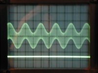
b) I'm now testing another "good" module and I've found that, even with the inputs shorted at ground, the module puts out a perfect 380 KHz sine wave, 1.2V peak-to-peak.
This sine wave modulates every other frequency I put through. The attached picture shows the output of the module with a 1KHz input signal. The peak-to-peak value of the output is 1V approx. (scope scale is 1V div)
Can anybody tell me if this is normal? So far I've only tested with a resitor load, I'm a little uneasy connecting my precious horns until I feel comfortable that everything is OK.
Please let me know your ideas and experiences.
I'm testing now my newly completed 6-channel power amp, UCD400 based, and I have run into several problems:
a) I inadvertedly started one module/channel (i.e. I connected the "on" pin to ground) without any load being connected to the output. In no time at all, I mean less tha a second after the blue led went on, a tendril of smoke came out of the coil and the LED went out. I haven't been able to start that module again ever since.
Does this mean that the module is fried? I thought that, unlike the LC Audio ones, the UCD were supposed to be immune from the lack of load. Mind you, I'm not talking about disconnecting the load at full power, I'm just talking about starting the module without any load. There's no mention of it in the instructions.
Can anybody shed some light? Is there a way to protect the modules?
b) I'm now testing another "good" module and I've found that, even with the inputs shorted at ground, the module puts out a perfect 380 KHz sine wave, 1.2V peak-to-peak.
This sine wave modulates every other frequency I put through. The attached picture shows the output of the module with a 1KHz input signal. The peak-to-peak value of the output is 1V approx. (scope scale is 1V div)
Can anybody tell me if this is normal? So far I've only tested with a resitor load, I'm a little uneasy connecting my precious horns until I feel comfortable that everything is OK.
Please let me know your ideas and experiences.
Attachments
The modules are NOT sensitive for switching on or off with or without a load. The UcD modules are UNCONDITIONAL stable. There must be something else wrong. Please send your complain to: support (at) hypex . nl , they will take care f your problem.m.parigi said:I've looked into the the UCD 400 thread but the information, if present at all, must be very thinly spread, because I haven't been able to find anything that would help me.
I'm testing now my newly completed 6-channel power amp, UCD400 based, and I have run into several problems:
a) I inadvertedly started one module/channel (i.e. I connected the "on" pin to ground) without any load being connected to the output. In no time at all, I mean less tha a second after the blue led went on, a tendril of smoke came out of the coil and the LED went out. I haven't been able to start that module again ever since.
Does this mean that the module is fried? I thought that, unlike the LC Audio ones, the UCD were supposed to be immune from the lack of load. Mind you, I'm not talking about disconnecting the load at full power, I'm just talking about starting the module without any load. There's no mention of it in the instructions.
Can anybody shed some light? Is there a way to protect the modules?
b) I'm now testing another "good" module and I've found that, even with the inputs shorted at ground, the module puts out a perfect 380 KHz sine wave, 1.2V peak-to-peak.
This sine wave modulates every other frequency I put through. The attached picture shows the output of the module with a 1KHz input signal. The peak-to-peak value of the output is 1V approx. (scope scale is 1V div)
Can anybody tell me if this is normal? So far I've only tested with a resitor load, I'm a little uneasy connecting my precious horns until I feel comfortable that everything is OK.
Please let me know your ideas and experiences. [/B]
This HF carrier is normal with a Class-D amplifier!
BTW: Happy New Year to everybody!
Cheers,
Jan-Peter
HF output of this kind is not a "normal" condition of calss D amplifiers.
I am concerned about the amplitude of the carrier-
are we talking about an amplifier with 50 V rails exhibiting an output 380KHz carrier at 1.2V? ( being a square wave the 1st, 3rd and 5th harmonic are dominant) if so I cannot see any real way this can pass EN 55103 pts 1&2- this has always been a worry to me with self resonant amplifiers with a second order output filter, in my commercial designs I have to use an eliptical output filter and a crystal locked triangle, natural sampling system to ensure reliable emc performance- I know hobbiests are immune from CE marking but anyone selling a module to consumers must comply, is this realy the noise level from the module, and where was the ground when this was measured? I presume on the speaker terminals, so what is the psu rail noise like??
I assume the unit is CE marked, and would like to see the classification of the tests inorder to comply with 55103-1, and 55103-2 (sorry American audience I know not of your FCC numbers), cause if you can get this thru with this noise I can save myself a shed load of cash on my products- BTW how is AM radio in the presenc of speaker leads radiating this signal?
regards
Again this is a complete normal behaviour for a Self Oscillating Class-D amplifier. Besides this you see a perfect sinwave of +/-400kHz, and no higher order frequencies.
All our products are CE certified.
Amoungst all other Class-D modules we are showing the lowest HF ripple residue and the lowest EMI output.
Jan-Peter
All our products are CE certified.
Amoungst all other Class-D modules we are showing the lowest HF ripple residue and the lowest EMI output.
Jan-Peter
Only a small correction...
I am sure Hypex are very good Class-D amplifiers.
However, please be sure that your records are updated: Coldamp BP4078 modules have less than 150mV rms ripple at +/-60V (that's nearly three times less than UcD) and very low EMI as well.
Best regards,
Sergio
www.coldamp.com
I am sure Hypex are very good Class-D amplifiers.
However, please be sure that your records are updated: Coldamp BP4078 modules have less than 150mV rms ripple at +/-60V (that's nearly three times less than UcD) and very low EMI as well.
Best regards,
Sergio
www.coldamp.com
Jan-Peter said:Again this is a complete normal behaviour for a Self Oscillating Class-D amplifier. Besides this you see a perfect sinwave of +/-400kHz, and no higher order frequencies.
All our products are CE certified.
Amoungst all other Class-D modules we are showing the lowest HF ripple residue and the lowest EMI output.
Jan-Peter
I'd be worried if it were really +/- 400kHz
ssanmor said:Only a small correction...
I am sure Hypex are very good Class-D amplifiers.
However, please be sure that your records are updated: Coldamp BP4078 modules have less than 150mV rms ripple at +/-60V (that's nearly three times less than UcD) and very low EMI as well.
Best regards,
Sergio
www.coldamp.com
Yet reportedly blank out a nearby AM radio, said your own distributor? UCD does not, then again that's at 44 volt rails.
Our distributor (the well known and reputated Elliott Sound Products for the not knowing) always makes people aware of potential problems of his products (or the ones he distributes). That's a good policy IMHO, although in practical use you won't find problems with our modules. If you read the complete article, though, you will find that he says that there was no problem as soon as the modules were enclosed in their case (and that the station he was talking about was FM, not AM, btw)
For example, my own 5ch. coldamp amplifier is just besides my tuner and TV with no problems at all, and no special cautions such as ferrites or EMI filters.
_ALL_ Class-D amps (including Hypex, ZAPPulse, Tripath, etc) produce some level of RFI emissions, negating so is not fair play I think.
Although the levels of a well built one (such as the ones mentioned including ColdAmp) are not likely to produce problems in the vast majority of setups, it is good to warn customers (specially when they are DIYers and hence not necessary RF experts) about the potential risk that it may happen. It is a question of good commercial practice.
Nevertheless, and as a side note, Rod comments are based on his experience with the prototype modules he received months ago, that have been improved in that aspect since then.
Hi Ssanmor,
I'm not firing at you but you stated your modules were lower EMI and so I simply must enquire.
As I stated before my UCD180's don't even have the special treatment of being inside a case and don't disturb an AM radio at all which is placed about 20' away in the same room. For the sake of argument, I just tested it with my alarm clock on a weak AM station, placed the clock within a foot from the open modules (again, no case), turned them on /off a few times and there's no audible noise induced on the radio at all, let alone blanking out an already weak station.
So what have you done to your modules to improve emissions since Rod Elliot's samples?
Regards,
Chris
Anthony C Smith said:HF output of this kind is not a "normal" condition of calss D amplifiers.
I am concerned about the amplitude of the carrier-
are we talking about an amplifier with 50 V rails exhibiting an output 380KHz carrier at 1.2V? ( being a square wave the 1st, 3rd and 5th harmonic are dominant) if so I cannot see any real way this can pass EN 55103 pts 1&2- this has always been a worry to me with self resonant amplifiers with a second order output filter, in my commercial designs I have to use an eliptical output filter and a crystal locked triangle, natural sampling system to ensure reliable emc performance- I know hobbiests are immune from CE marking but anyone selling a module to consumers must comply, is this realy the noise level from the module, and where was the ground when this was measured? I presume on the speaker terminals, so what is the psu rail noise like??
I assume the unit is CE marked, and would like to see the classification of the tests inorder to comply with 55103-1, and 55103-2 (sorry American audience I know not of your FCC numbers), cause if you can get this thru with this noise I can save myself a shed load of cash on my products- BTW how is AM radio in the presenc of speaker leads radiating this signal?
regards
The last time you mentioned naturally sampled you also mentioned phase shift modulation, it was confusing.
You dont' get phase shift modulators which are clock based though, if you have phase shift modulation it's because it's a self oscillating amp.
I also dont' believe you get natural sampling with a clock based solution, as it's the clock that in fact controls the sampling, with all it's errors, same with the carrier you derive from it.
I understand your use of the term but find it purely academic, in that the clock based carrier naturally samples the input signal.
I don't believe you can get more natural sampling than with a self oscillating amp.
Your solutions tends to be geared towards making it easier to filter out any remaining carrier in that it is locked at a given frequency. The left over ripple from a self oscillating amp however does not define it's "noise" in any shape or form. Emissions would have far more to do with layout and good design decisions, proper choice of components etc.
Regards,
Chris
I hope you understand that I won't give you very detailed information about that, but these are some points:
- We have tuned our sw. frequency to be supressed more precisely by the notch filter. That allows us to reach almost 50dB of carrier supression at the sw. frequency.
However, that frequency is not the only harmful one for EMI, as Jan Peter noted. It is good to reduce HF ringing as well. In this aspect,
- We touched the mosfet drive circuit.
- We redesigned the winding of the main filter inductor in order to minimize leakage inductance further.
BTW: I also use "natural sampling" term for our products. That's the academic name for a form of clock-based PWM, doesn't mean it is "more natural" or "less natural" than other forms of modulation. Don't pay it much more attention.
I will stop here as the purpose of this thread (and even of this forums) are not advertise commercial equipment. I follow the policy of trying to clarify things when our products are mentioned and I consider it necessary.
Best regards
ssanmor said:I hope you understand that I won't give you very detailed information about that, but these are some points:
- We have tuned our sw. frequency to be supressed more precisely by the notch filter. That allows us to reach almost 50dB of carrier supression at the sw. frequency.
However, that frequency is not the only harmful one for EMI, as Jan Peter noted. It is good to reduce HF ringing as well. In this aspect,
- We touched the mosfet drive circuit.
- We retouched the winding of the main filter to minimize leakage inductance further.
BTW: I also use "natural sampling" term for our products. That's the academic name for a form of clock-based PWM, doesn't mean it is "more natural" or "less natural" than other forms of modulation. Don't pay it much more attention.
I will stop here as the purpose of this thread (and even of this forums) are not advertise commercial equipment. I follow the policy of trying to clarify things when our products are mentioned and I consider it necessary.
Best regards
Hi Ssanmor,
I appreciate your response once again, and if you spot the post I squeezed in above you'll note we're in agreement about the academic value of it, however I do really feel given the divide of self oscillating amps with clocked based ones it is far more correct to give the term "naturally sampled" to self oscillating ones by far.
I also see it as a matter of confusion for many who dont' realize what we've both pointed out, but I wont' go so far as to say it's incorrect to use it for your product at all.
I also do understand that you dont' want to give too much away, and that's no problem, I appreciate your response, and you still spoke volumes.
I know you're not here to advertise, you did give your product a bit of a plug though, indirectly and otherwise. To now claim you're not here to market, perhaps, in order to avoid a question or two doesn't look good to me.
If you want to get people curiouse about your product that's very OK we'd all love to hear about it, but you'll have to be there to answer the questions as best you can. Just my aimless view.
I think I'm now done posting for a long while now, I can see myself getting under the skin of many these days, and perhaps even enjoying it too much, even if it's not the intention. Seems like it's all been said already anyway.
Still, hope your amp does well for you.
Regards,
Chris
No problem, Chris.
it is good that people talks about one's products and you are not bothering us at all.
I will try to answer questions about my products as far as I can, but you all have to understand that there is also a lot of competence that can take advantage of our develpments for their own profit, and that's not fair. No one with commercial interest will reveal all his product details in an open forum, that's normal, isn't it?
Best regards,
Sergio
Hi Sergio,
Thanks 🙂 I just need a breather maybe.
I wouldn't want to see anyone steal from you, or anyone such as you who obviously did alot of hard work, spent time and money on R&D, and deserve your just rewards.
At the same time, if they really wanted to, it will happen regardless of what little tips you might decide to disclose here, however so indirectly, in order to help educate and advance the movement or individuals. So I'd hope the possibility of theft doesn't scare you away from that.
Though you've already contributed plenty. That said I know your supplies will do very well also.
I think it's great you got Rod Elliot as a distributor.
His site is one of the best out there I think, certainly he's in the spirit of things.
Best Regards,
Chris
This still did not answer the class of pass in en55103, nor the behaviour of am radios in the presence of speaker leads containing this signal.
Just for further info;
AM radio is usually obliterated by 180-700KHz magnetically radiated products, especially from speaker lines;
FM radio is usually obliterated by fet switching products from the heatsink and closed loop on the pcb.
Using a fixed frequency oscillator has the benifit that a fourth order eliptical filter can be designed at the sampling rate and twice the sampling rate, this combined with a phase shift amplifier and common mode output choke means you can realy achieve a residule sampling component of 12mV RMS in 100V RMS output- I do, and with proper pcb, heatsing and overall emc design, including the casing you can run with an am radio, or fm radio sat on top of the unit.
I am not knocking the hypex unit, I am suprised at the HF output level, and in the case of the cold amp unit I would be ware of a casual comment that it blocks out radio (am or Fm) without trying it myself- urban myths are quite common in this industry!!
regards
The HF ripple must be one of the most overstated "problems" of class D amplifiers around.
Myth #1: "The HF will fry my tweeter.". A tweeter is an inductive device. At high frequencies the equivalent impedance is a series network of an inductor (the voice coil inductance) and a resistor (the copper resistance) and a large parallel resistance (modeling the eddy losses in the pole pieces). The latter may be largely ignored.
Suppose you have a typical tweeter with 6 ohms of resistance. At 300kHz, impedance is more along the lines of 30 ohms. If the amp puts out 400mV worth of carrier, this translates into 13mA of current. This current produces dissipation only in the resistive part of the impedance, so that's 6ohms*0.013mA^2=1mW. ONE milliwatt. You need around 250mW to stew an ant, so one milliwatt won't fry a tweeter.
Myth #2: "The HF will cause intermodulation effects". Leaving aside the obvious fact that you need something else to mix against, I'd like to quote from a test done to determine if intermodulation effects might account for reported audibility of spectral content above 20kHz. To this end, researchers fed a pair of large test tones of just above 20kHz to a tweeter. What they discovered was that the only audible intermodulation products were caused by the amplifier, not the tweeter (and also not the human ear). If large near-audio-band tones don't produce intermod effects, smaller signals much higher up certainly won't.
Myth #3: "The HF will radiate from my speaker cables". This is actually the only myth with some root in reality. Some. A cable becomes an efficient antenna once its length approaches a quarter of the electrical wavelength of the signal. 300kHz has a wavelength of around a kilometer. If you're planning to attach 250m of cable to your amp, fit a good common mode choke to the output, please?
The RF that is truly a problem in realistic systems are the higher frequency components emanating from the power stage that the output filter failed to attenuate sufficiently. All power filters are limited at really high frequencies because the coil has a parasitic shunt capacitance and the cap has a parasitic series inductance. You can see that on a scope. When you zoom in on the switching ripple, you'll see a small "blip" right after the zero crossings. This is when the power stage transitions. If it's a "blip" (say a few tens of mV that quickly rings out), that's fine. However, I've seen competing products (the new power generation or how was it called I can't remember) where the amplitude of the switchover transient was larger than the 400kHz residual and went on until next switching transition. Oops. Even with no other cables attached than mains all radios in the building went dead when the unit was turned on.
Myth #4: "This is typical of self-oscillating amps". This is a brand-new myth just spotted in this thread. All class D amps use a large square carrier and a lowpass filter. That's what they do. The result is necessarily a small sine-like residual after filtering. The nice thing about having post-filter feedback is that you can set the filter cut-off frequency lower than with amps that don't have feedback (like "digital" amps which are obviously non-self-oscillating). You can make full bridge amps with the two halves operating in phase HF-wise and out-of-phase LF-wise, thus nearly eliminating the differential-mode residual. You can make such amps self-oscillating or clocked with equal ease. In other words, the presence of a residual has not one bit to do with the modulation scheme.
I hope this clarifies matters a bit.
Hi Athony,
It's not an urban myth but a review by the distributor, although the designer already explained that was on a previous version and it's been improved from then somewhat, I'm the last person to want to fuel a myth in this industry I assure you of that.
Would said clocked unit still maintain a 12mV RMS output, at idle?
If you're surprised at the HF level of ripple, I should also let you know that my speaker wires are over 12' long, the radio was plugged into the same outlet as the amp, no enclosure used over the modules or their supply. The power cord cord of the radio ran // to the speaker wire for a good 5 feet, and not enough EMI to be audible on the radio.
No common mode chokes employed on the outputs either.
Given that level of EMI performance, with that level of ripple, there's obviously got to be more to the story, and in the least it would seem such measures as you stated (while all are good) aren't necessarily required.
It seems like alot of engineering can go into what may be in fact an imagined problem given an ideal layout, and/or, certain techniques need to be more commonly known.
Regards,
Chris
- Status
- Not open for further replies.
- Home
- Amplifiers
- Class D
- Jan-Peter, anybody, help with UCD400 issues!