More like fighting words........😀
As long as you are Darth Vader, then you're ok.
Hahahaha
It's too early in the morning......
....any thoughts? 😉
Jam
....any thoughts? 😉
Jam
Attachments

Last edited:
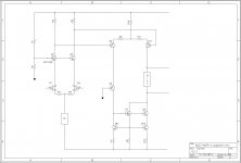
I believe I see three suggestions here:
1) degenerate both LTPs
2) improve the current mirror in the second
3) Q5, but I have no idea what it's doing
It's also upside down, but I assume that's just to use easier-to-find N-channel JFETs? (I happen to have some 2SJ109s burning a hole in the bottom of a drawer, so I like the other orientation.)
I'm going to play with (1) first because stability is still marginal with a decent slew rate and perhaps I can increase the current for better slew rate without increasing the gain.
Jam your Q5 is the wrong gender. As drawn it will push gerbillions of amperes thru R9. And R7 & R12.

Last edited:
Jeff,
Degeneration on second diff is slight or can be removed........just a matter of balance.
Jam
Degeneration on second diff is slight or can be removed........just a matter of balance.
Jam
Most degeneration I've seen has been on the order of 100 ohms. Can I use something like 5 or 10 ohms in the first diff, or would that be pointless?
(Otherwise I need bigger resistors in the legs to get the gain back, and then I run out of voltage on the negative swing.)
(Otherwise I need bigger resistors in the legs to get the gain back, and then I run out of voltage on the negative swing.)
I didn't have to use that little after all. With 47R in the first diff I'm getting 50uV/sec and DC - 100kHz frequency response with reasonable margins (45º and 7dB). Whoo hooo!
It's difficult to balance the comp strategies because I need Miller compensation for the gain margin, phase lead compensation for the phase margin, and input filtering to move both back a bit.
I tried transitional Miller, and Miller around the output stage, but had no joy.
It's difficult to balance the comp strategies because I need Miller compensation for the gain margin, phase lead compensation for the phase margin, and input filtering to move both back a bit.
I tried transitional Miller, and Miller around the output stage, but had no joy.
at the currents you're showing in R10, R11, and R23, that's a fair amount of wasted volts (headroom loss) and resistor warmth ...
mlloyd1
mlloyd1
Jeff,
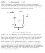
Michael has a point (but if you make the front end rails high enough and reduced the current in the second differential since you have drivers)........I woulds still address early effect in the mirror and improve its accuracy.
Jam
Michael has a point (but if you make the front end rails high enough and reduced the current in the second differential since you have drivers)........I woulds still address early effect in the mirror and improve its accuracy.
Jam
Attachments
Last edited:
Jeff,
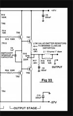
Also try removing the connection of the driver emitter resistors to the output, it might reduce crossover distortion.
Jam
Also try removing the connection of the driver emitter resistors to the output, it might reduce crossover distortion.
Jam
Last edited:
at the currents you're showing in R10, R11, and R23, that's a fair amount of wasted volts (headroom loss) and resistor warmth ...
mlloyd1
I'll have to have a look at that again. Boosting the second diff current was the only way I could get the slew rate up. But I have no Miller comp on the drivers, so I'm not sure what the extra current is required for....
Cheers,
Jeff.
Jeff,
Also try removing the connection of the driver emitter resistors to the output, it might reduce crossover distortion.
Jam
Another thing I need to give another go at. When I tried that earlier something went haywire. (I think it was the phase angle, but I can't remember.)
But cross-over distortion? Pfffft. What cross-over? This baby's biased at 3A!

But cross-over distortion? Pfffft. What cross-over? This baby's biased at 3A!
I think he is referring to R32, R33
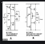
Pico is correct. If R32 and R33 are connected to the output there may be added asymmetry during zero-cross. I think it was James Bongiono was the first to point this out, I will try to find the relevant article.
Jam
Jam
Doug Self has also noted this in the design of his Blameless Amplifier. 🙂
Switching speed seems to be the issue here. Granted the example is for bi-ploars it remains to be seen what it does in the Buzz Bomb,
Jam
Switching speed seems to be the issue here. Granted the example is for bi-ploars it remains to be seen what it does in the Buzz Bomb,
Jam
Attachments
Last edited:
- Home
- Amplifiers
- Pass Labs
- JamJar: an HPA-1-inspired power amp