While looking over the schematic for this OTL amplifier I noticed something odd.
Lee 6C33C OTL
It looks fairly straight forward until you see +/- 180v power supply. Its really not a split supply. The output from the tubes goes through the speaker and then to the middle of the two 1000uf caps. Most other OTL amps have a true split supply with the center being ground.
The link to the original article is long gone although I recall seeing it years ago, say 1996 or so. So any thoughts or opinions on this design?
No expert (by any means) but the PI on this looks way cool -- is it 1/2 triode / 1/2 pentode? -- my little brain is reeling. What *is* that 12BY7 doin' in this circuit? I gotta play with this topology as a driver toward more common tubes like 6aq5s, 6x6, el84s. Any thoughts on that would be of real interest to me.
But on the PS issue -- is the 6c33c tube (aside from crazy high output/plate) worth all the trouble?? Is there a 6c33c evangelist in the house?!?! Wow -- straange iron -- maybe he is hiding others under the covers but if not -- that is one multi-tap xformer - huh? Not sure I know enough to appreciate the implications of the +/- 180V - but it is different.
Very cool schematic -- thanks for posting it.
Last edited:
The output is connected to the junction of the two caps at ground. Nothing at all unusual there.
The 12BY7 is a current sink, with feedback to the cathode from the output.
The 12BY7 is a current sink, with feedback to the cathode from the output.
Yeah, if the bias current of the two 6C33 is not perfectly matched, those capacitors charge up toward one rail. Needs some zeners/ resistors across them to handle bias current mismatch.
The other thing I notice is that one 6C33 is operating as a follower, and the other is operating with gain. Needs a bootstrap resistor/cap from the output back to one of the 12BH7 plate load resistors (top end) to equalize output gains.
I also see a 20K Ohm pot from the output back to the 12BY7 cathode, that is modulating the tail current for the 12BH7. Maybe this has the effect of equalizing the output tube gains, strange way to do that. Variable slew rate.
Last edited:
Hi Don;
another option is to turn the bottom tube in a linear voltage to current converter. Kind of Pyramid-III concept.
I did similar things with 12L6GT, with capacitive coupled auto transformer, before coming to conclusion that power MOSFETs are much more optimal to drive modern speakers than any tube you can find/design/build.
I don't like the circuit as there is no designed in way to have the lower output tube have exactly the same gain as the top tube, i.e.slightly less than one.
The OTL in the latest copy of "Audio Express" is the best OTL circuit I've ever seen, very low distortion without any NFB, because he uses the lower output tube as a gain defined anode follower. Wll thought out, good design!
Regards, Allen
The OTL in the latest copy of "Audio Express" is the best OTL circuit I've ever seen, very low distortion without any NFB, because he uses the lower output tube as a gain defined anode follower. Wll thought out, good design!
Regards, Allen
I don't like the circuit as there is no designed in way to have the lower output tube have exactly the same gain as the top tube, i.e.slightly less than one.
The OTL in the latest copy of "Audio Express" is the best OTL circuit I've ever seen, very low distortion without any NFB, because he uses the lower output tube as a gain defined anode follower. Wll thought out, good design!
Regards, Allen
For those without access to a copy, please post the circuit
Andy
.
For those without access to a copy, please post the circuit
Andy
.
As requested.
Attachments
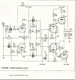
I find the use of neon bulbs and spark gaps interesting...
To me it looks like the bottom tube in the output is basically a voltage controlled current source that modulates the current in the source follower (top output tube). Seems almost classA-ish...
~Tom
To me it looks like the bottom tube in the output is basically a voltage controlled current source that modulates the current in the source follower (top output tube). Seems almost classA-ish...
~Tom
[QUOTE
The OTL in the latest copy of "Audio Express" is the best OTL circuit I've ever seen, very low distortion without any NFB, because he uses the lower output tube as a gain defined anode follower. Wll thought out, good design!
[/QUOTE]
Reading the article in Audio Express gives various information about the distortion levels achieved with this circuit. In the text it is mentioned 0.14% at 2W without feedback and 0.007% with feedback while in the distortion plot the 3rd order product is at approx 45dB below the fundamental which then is about 0.5%. It could be so that the author refers to the 2nd order products only, they are at about -55dB in the plot which is close to the mentioned 0.14%, he also talk about achieving very good balance an low even harmonics in the text.
Last edited:
- Status
- Not open for further replies.
- Home
- Amplifiers
- Tubes / Valves
- Jaehong Lee OTL