This is what a real expert says about a woofer with Fs =
26 and Qts = .67 and some suggested Ripole design.
I suppose a search in the forums always is good.
/Erling
Hi,
A "real" expert ? how can you tell ? I can't.
Anyway here with DSP on the bass and an amplifier not shy
of chucking out loads of watts the real issue is how loud
versus how low you want to go for a given baffle roll-off.
I haven't measured the Q, but with my H-baffles, Fs goes
down from 33 to 25 Hz from the air loading. That's quite a bit!
Hi,
That implies air mass loading of about 70% of cone mass.
Correct me if i'm wrong but that implies a stupendously
useless bass driver for any sort of box, sealed or vented.
Nobody makes such a driver, they simply don't exist.
rgds, sreten.
Last edited:
Erik, understand that, sreten have made an open baffle only on paper and he is now an expert
His comment is useful
Better to smile
Yes Erik, in an OB, I confirm the Fs becomes lower and the Qts higher with the same ratio
That is my experience as well.
It's everybody's experience, including God himself (Linkwitz that is). How much Fs and Qts is affected depends on the baffle type and size I would imagine, although I've never seen any study on this. I've experience more Fs and Qts change with H-baffles than with flat baffles or U-baffles. I guess the air load is larger with H-baffles.
It really depends on the details of the configuration. In my U-frames with the heave cone XXLS woofers, I don't see any significant change in the undamped Fs and Q. But that doesn't really matter too much because to make the U work correctly requires significant damping of the U-frame. The damping plays a much more dominant roll in altering the response of the woofer then the air mass load of the U.
Also a significant affect is the relative cross-sectional area to length ratio. This not only effects the mass loading but also the strength of the 1/4 wave resonance of the enclosure. If the area is large compared to length there will be less of both. The Ripole is unique in that the area can be rather small, smaller than Sd.
Also a significant affect is the relative cross-sectional area to length ratio. This not only effects the mass loading but also the strength of the 1/4 wave resonance of the enclosure. If the area is large compared to length there will be less of both. The Ripole is unique in that the area can be rather small, smaller than Sd.
Yet an other useful comment from sreten. Thanks a lot.
Hi,
If you can't address the technical issue raised don't make sarky comments.
I simply stated that no arrangement that I'm aware of will add an additional
mass loading equivalent to 70% of cone mass, for any driver I'm aware of.
I don't know what or how you measured what you say. I do know that
it doesn't fit the theory, and that knowledge is not gained by basing
your theory on measurements that don't make much sense.
rgds, sreten.
MJK
The measured results for the Goldwood GW-1858 are shown in
Figures 10, 11, and 12. Comparing impedance plots shown in
Figures 10 and 11 the shift in the driver’s resonant frequency
can be seen clearly.
The original 30 Hz fs has dropped to just under 28 Hz while the
Qts has risen from 0.905 to 1.040 when the Goldwood woofer
was taken from the test baffle and mounted in the H frame.
Last edited:
For drivers with large excursion the front opening should be not less than 1/3 Sd. The back opening should be 1/2 to 1/1 of Sd. The cross area of the back opening is not critical. Make the back chamber as wide as is helpful for the construction.
Considering the really large Xmax of the driver I would make the front opening 15-16 cm wide.
Rudolf
Rudolf,
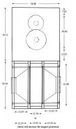
Thanks, this allows me to begin drawing up the design, I am thinking it will be a 2 piece affair, with the Ripole module measuring 53.34 cm width x 45.72 cm height and depth. The open baffle for the mid and tweeter will sit on top of the Ripole 54.34cm wide by 61.00 cm height and be tilted back 5 degrees supported by triangular side stays. This may be revised once I finish the drawings and begin to envision the scale and size. The material will be 25mm Baltic Birch that most likely be veneered. The bass drivers should be delivered in a week or two but given other commitments, the time frame for the completed project remains open. However I will begin on the open baffle sometime next week. Because I do not own a table saw I will probably contract out the cutting of the panels, leaving me with the routing and assembly.
Cheers to all who have contributed to this project
Vanko
Rudolf or others,
After some preliminary drawings and estimations, I found that I did not want to increase the width of the Ripole module and revised the the common slot opening for the Dayton Titanic 15" driver so that it would remain at between either 12.7 cm or 13.97 cm width but increase the height of the opening from 39.37 cm to 45.08 cm to offset the loss of area. I would like to keep the width of the Ripole at no more than 50.8 cm with the magnets of the drivers protruding no further then 1.27 cm on the sides. The back channel for each individual driver I have calculated at either 13.97cm or 13.33 cm width by 45cm height, the width of the back side being determined by width of the slot on the front side. I just want to know that in a Ripole design that so long the area remains constant that I can vary the width and height of the front slot opening.
Cheers,
Vanko
Hi,
Just an observation about the shape of the ripole, or whatever its called,
I'm no expert. With a squared off W shape and down being pointed
forward you have two opening to the rear and one to the front.
It makes more sense the front opening is wider than the rear
two openings, though what difference it will make I'm not sure.
As drawn I assume the point is to hide the bass drivers from the front.
An alternative is to mount one driver in the central section out of phase.
You still get force cancelling but you also get 2nd harmonic cancelling.
See S.L.'s Orion 4.
rgds, sreten.
Vanko,
Go ahead and build even if you miss Rudolf with 1 cm or 2.
I am afraid that sreten just demonstrated that he knows nothing whatsoever about the Ripole.
One thing that might be a bit more problematic is the bass/mid crossover. You would choose to cross no higher than 150 Hz I assume, and perhaps preferably lower. Given your baffle dimensions I suspect that you also have to EQ the midrange to get a perfect crossover.
/Erling
Rudolf or others,
After some preliminary drawings and estimations, I found that I did not want to increase the width of the Ripole module and revised the the common slot opening for the Dayton Titanic 15" driver so that it would remain at between either 12.7 cm or 13.97 cm width but increase the height of the opening from 39.37 cm to 45.08 cm to offset the loss of area. I would like to keep the width of the Ripole at no more than 50.8 cm with the magnets of the drivers protruding no further then 1.27 cm on the sides. The back channel for each individual driver I have calculated at either 13.97cm or 13.33 cm width by 45cm height, the width of the back side being determined by width of the slot on the front side. I just want to know that in a Ripole design that so long the area remains constant that I can vary the width and height of the front slot opening.
Vanko,
I get the impression that you are not really prepared to do some own development (one or two test builts), but want the optimal dipole dimensions just from the start. In this case you will be best advised to contact Axel Ridtahler directly. I know that he is prepared to give you precise dimensions and the needed passive EQ network for a small fee - compared to your investion in drivers. He will need the individually measured TSP of your drivers (not from the factory datasheet!) or could do the measurements himself - if you send him a driver).
Please understand that I can't expose his email adress in an open forum for obvious reasons. That's why I will write it in a PM.
Hope this helps
Rudolf
PS: Don't look at post #32. Consider post #33. I really can't give you any competent advice whether one of your variants would be better than the other. Both are at least reasonable. Ridtahler will know better.
")
Hi,
Well I don't know if I am as competent as an expert regarding dipoles, but I certainly know what a Ripole is and how to design it so that it works properly, even if I wouldn't use the same simulation script Axel wrote?
The Ripole shares obvious similarities to Linkwitz's W-frame dipoles. But it also has distinct differences, the most obvious its smaller size. The smaller size leads to differing requirements regarding the drivers parameters. With the larger sized SL's the reduction of the freeair resonance is small, nearly negligible. As such drivers like the Peerless XXLS are suitable. I'd regard the afore mentioned Dayton Titanic 400 also suitable for useage in a SL-dipole. it's low Fs may sink to 20-22Hz, but not much down into the infrasonic range. The high Qts helps to keep equalization requirements a bit lower than with low-Qts drivers. The Daytons basket and Magnet build deep. This alone sets a lower size limit rather like in a SL-dipole than in a Ripole. Its excursion capability asks for a larger front chamber size (the 1/3-rule should be regarded as a rough hint not a fixed value). Built into a Ripole I'm afraid would lead to suboptimal results with this driver. I'd expect at least a Fs-reduction down into the infrasonic range and probabely turbulant noise at high excursion levels.
The large cone drivers of the 15" and 18" class that suit well into a Ripole concept are more often be found in the catalogues of PA manufacturers than in HiFi. The Beyma LX-series for example looks promising and has a low height profile. Very well suited HiFi-drivers for Ripoles are the Peerless SLS10 and 12.
Since the Ripole reduces the Fs considerably (expect 5-10hz and up to 15 Hz in extremes) a Fs-range of 30-35Hz is optimal. Ripoles typically feature higher Qts drivers. A range starting at 0.35 for large drivers up to 0.7 for smaller drivers.
Ripoles also feature a passive eq-network, which not only notches the chamber resonance peak, but also influences on Qts and Fs.
I'm online with IPad so I can't do a sim right now. But I'll see what I can do tomorrow.
jauu
Calvin
Last edited:
A cheap and fast build using two 12" Polk DXI 124 SVC. DXi124 - Car Subwoofers | Polk Audio
Some things have come up in life, so I haven't had time to finish assembling their new enclosures.


FYI, the rise in distortion from 60-110hz was mainly due to cabinet resonances. I was able to shift the distortion level and frequency by pressing on the side walls. New enclosures made of baltic birch and with tighter tolerances will fix this.
Some things have come up in life, so I haven't had time to finish assembling their new enclosures.
FYI, the rise in distortion from 60-110hz was mainly due to cabinet resonances. I was able to shift the distortion level and frequency by pressing on the side walls. New enclosures made of baltic birch and with tighter tolerances will fix this.
Thank you Calvin for your help,
I have been scrambling to cancel the order for the Dayton Titanic drivers before they ship but will not know anything until Monday as Parts Express is closed until then. Are you talking about the Beyma 15LX60 and 18LX60 (both were on my short list until I decided to inquire about the Ciare NDH15-4s) What I am trying to achieve is a foot print of no wider then 20" (50.8 cm) yet be able to play 100 db somewhere in the 30's. If worse comes to worse, I can augment them with the sealed seas L26ROY subs that I built for the TJL3W Project but that would require me to purchase another amplifer. My interest in this project is the presentation and sound of a open baffle speaker including bass on a reasonable sized footprint. Given that choice on Ripoles, I would rather build 2 big ones then 4 little ones. US Price for the Beyma's are as follows:
15LX60 $320
18LX60 $330
Cheers,
Vanko
Attached is a rough drawing with the variations describe in previous post,
Vanko
Hi,
You should simulate the response in the mid on the 50cm panel , you will have a big hole in the 500Hz..2kHz and a bad sound in this area.
You should offset the mid.
Open baffle is more far difficult than box speaker.
See Jamo measurement OB : Jamo Reference R 907 loudspeaker Measurements | Stereophile.com
Not for nothing Linkwitz has made the dimension of his Orion...
Just my 2c.
Hi,
did a first Ripole-sim for the TIT400-C4 pair in parallel connection.
The dimensions of the Ripole based on 12 plywood:
W: 508mm H: 502mm D: 419mm
Front chamber: H:450.8mm W:136mm The front port´s area is increased to a factor of 2xSd/2.62
Back chambers: H: 450.8mm W:135mm
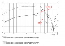
The first graphic shows the amplitude response without filter @2.83V and with filter @ 2.83V and 25V.
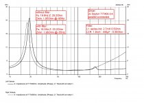
The second graph shows the impedance response.
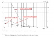
The third graph shows the excursion over frequnecy and voltage.
You can see that the filter cleans up the amplitude response nicely, it lowers the Fs and increases Qts slightly. Excursion limit @20Hz is reached with 25V of signal voltage, resulting in an SPL of ~108dB@1m. Beeing a 4Ohm driver the parallel connection halves the impedance, which is furthermore slightly lowered by the passive filter. The amp should be 2-Ohm stable.
Thats all for now Folks
jauu
Calvin
did a first Ripole-sim for the TIT400-C4 pair in parallel connection.
The dimensions of the Ripole based on 12 plywood:
W: 508mm H: 502mm D: 419mm
Front chamber: H:450.8mm W:136mm The front port´s area is increased to a factor of 2xSd/2.62
Back chambers: H: 450.8mm W:135mm
The first graphic shows the amplitude response without filter @2.83V and with filter @ 2.83V and 25V.
The second graph shows the impedance response.
The third graph shows the excursion over frequnecy and voltage.
You can see that the filter cleans up the amplitude response nicely, it lowers the Fs and increases Qts slightly. Excursion limit @20Hz is reached with 25V of signal voltage, resulting in an SPL of ~108dB@1m. Beeing a 4Ohm driver the parallel connection halves the impedance, which is furthermore slightly lowered by the passive filter. The amp should be 2-Ohm stable.
Thats all for now Folks
jauu
Calvin
Attachments
Last edited:
Hi,
a sim with in series connected TIT400-C4 gave similar results wo filter, apart from of course the impedance plot beeing higher. But it was impossible (at a first shot) to design the passive filter with a similar linear amplitude response a with paralölel connection and which´s impedance didn´t drop below 2Ohms around the chamber resonance point. So I didn´t include these sims here.
jauu
Calvin
- Status
- This old topic is closed. If you want to reopen this topic, contact a moderator using the "Report Post" button.
- Home
- Loudspeakers
- Multi-Way
- JA8008/TWO34 open baffle/ripole project