Thank you, Jay, but it is a bit offensive to me, that people suppose that I could still learn such a things like you are saying.
I don’t understand which part is the offensive one. Of course I can see that you are among a few people who use such a big transformer 😀
I have read also that some DIYers used overrated transformer without trying to understand the math (they just used their ears and experience). But this is also not a popular approach isn’t it? So deserve to be brought to surface also.
Big part of amps, that give no chance for laughing at the distortions, nevertheless can be deposited as trash.
Agree.
Thinking about hidden reasons, that could prevent one or another schematics from producing natural sound, seems most interesting for genuine DIYer. There are "superficial" features, like THD, IMD, output cap, pass band, and many of us tend to ascribe them an excessive importance.
Natural sound??? I myself don't even care about it. There are even more disastrous things that can happen to sound in speaker reproduction. What I need from my (relatively good) amps, is that they should not introduce fatigue (Speakers are even more critical here). Many things can cause this fatigue in an amp: wrong capacitors, wrong diode, fake transistors, even wrong transformer! But being critical DIYers, using good (often expensive) components will often save us from this problem (though not always).
And there must be those "superficial" features in an amp that make it more fatiguing than the other. That's why I value such low TIM design such as the Leach or the Otala. Class AB distortion is a good example of the cause of fatigue, but so is the error correction schemes?
... I also use SE 300B tube amp for estimating sound transparency. For on-the-bench tests, I use small Castle Acoustics Pembroke, that are very transparent nevertheless.
Of course there's nothing wrong with such approach (everybody is doing it). But using parameters like transparency, sonic, bla bla bla in choosing amps is often like chasing a ghost.
So that's it! And we have to agree on thing like this in order not to chase a ghost. But "presence" can be defined differently and wrongly.Good sound = effect of presence at live event.
I think none of amp design parameters can explain this clearly, but many things in speaker design can (such as reflection etc)
And after assembling and testing of many schematics, I can state, the schematics that no shining at the first test, it could be improved at the final form (by using expensive PS arrangement etc.), but it will not become excellent. We need more real tests reports from DIY community..
The problem is we need to select these "reports". It is okay for me, as I have been long enough here so I know whose I can trust (you included). But I think it is not about how long I have been here. It is about how I trust my ears, so I can trust those who have the "same ears".
And amp quality is highly affected by good power supply especially for the line level (front end). There is just not enough example of high voltage power supply on the net so I cannot find out which amp is better with which suitable front end power supply. Of course, I have used those used by commercial amplifiers, but those circuits created by DIY "enthusiast" are often better. Can you suggest one that I can use for all my amplifiers?
There is just not enough example of high voltage power supply on the net so I cannot find out which amp is better with which suitable front end power supply. Of course, I have used those used by commercial amplifiers, but those circuits created by DIY "enthusiast" are often better. Can you suggest one that I can use for all my amplifiers?
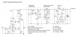
This is my high-voltage SS preamp, with simple parametric-like (no NFB) shunt power supply. Excuse me for notions in russian, but I guess the schematics is simple and quite clear. Design needs transistor matching, since it has no NFB. Voltage amplification 22dB. Maximum output voltage swing 80V peak-to-peak.
VT8,9 - current source
VT6,7 - zener substitute
VT4,5 - zener power booster
VT1 - high Idss j-FET (Idss=600mA), Ciss=12pF
VT2,3 - russian SIT transistors KP926A (something resembling 2SK60 from SONY)
I believe, this shunt PS schematics is just OK, using more complicated ones with NFB loops can be counterproductive.
Attachments

Don't let it fool you, since it counter amplifies the rail against the reference, that is feedback.😉 Nice clean conceptual work as always. Well done.
Hi Vladimir,
Thanks for your circuits. Actually I have been planning to build your integrated follower with the lower 60V supply. With this one I won't be worrying the input bias.
I have bought 2kV transformer that I plan to put in a wooden cabinet acting as the "table" for my amps. This separate power supply will feed 4x or 6x of my amps. These "final" amps are supposed to drive an active speaker system in the future. I have a worry if this big transformer will be good enough as it is a local product and is EI one, even tho I bought the most expensive I could find (my smaller transformers are undoubtedly better).
The maximum rail of the transformer is +-74Vdc (after *1.44). And I have only 4 pieces of IRF331 (TO-3). So for a mono amp I will use 2 pieces of IRF331 in the lower part and 2 pieces of IRF150 (TO-3) in the upper part). Rail voltage will follow this and the heatsinking scheme.
I want to find out which amps that I want to settle with (before burying my head on active crossover design), your amp (which is a class-A, but in a lower quality versions due to transistors availability) or the others (Stochino's, Mooly's, Mimesis3). To find out which, I need a good front end power supply for those class-B amps. Yes, I have been looking at the shunt supply you used, and I have tried to "copy" it for the negative side, but I'm not sure that I did it correctly 😀 (So if you have the split version, please share it with me)
I have a worry if this big transformer will be good enough as it is a local product and is EI one, even tho I bought the most expensive I could find (my smaller transformers are undoubtedly better).
Usually the requirements of trafo efficiency (the first place at industrial applications) do not coincide with absence of elecro-mechanical noise requirement.
Actually I had to use 400/110V 1kVA trafos. Being fed from 230V, it is dead silent and gives 63V at the secondary, that is quite comfortable for PS with choke input, or for regulated PS.
Vladimir,
Nice circuit. Consider this: Halve R2 to 6K8, connect top to drain of VT2. Remove C1, HL1-3, connect 1K5 in place of C1.
Ultra-linear cascode?
Hugh
Nice circuit. Consider this: Halve R2 to 6K8, connect top to drain of VT2. Remove C1, HL1-3, connect 1K5 in place of C1.
Ultra-linear cascode?
Hugh
Vladimir,
Nice circuit. Consider this: Halve R2 to 6K8, connect top to drain of VT2. Remove C1, HL1-3, connect 1K5 in place of C1.
Ultra-linear cascode?
Hugh
I afraid, the big gate capacitances of VT2, VT3 (2000pF) can cause some problems in the version you propose, although your idea is nice and thanks for creative look on the things.
You can always tie the voltage divider to the base of an EF; that would shake rather than stiir the gate, n'est pas?
Hugh
Hugh
So Hugh you dont fancy the led based voltage reference...but prefer a simpler resistor based..?? To some degree i understand this, where you have the smooth shunted Top rail...
Afraid of the LED uV noise..???
Afraid of the LED uV noise..???
MiiB,
Different case..... what I propose is modulating the base of the cascoding jfet at half the AC output to confer a type of ultra-linear operation. This has advantages in that it promotes even over odd harmonic generation.
I have nothing against LEDs as voltage references for CCSs and use them in most of my amps. I also like bootstraps, since by varying the resistor ratio one can tailor the harmonic profile as well as load up the amplifying device at higher frequencies when the ESR of the electro rises. This helps with Bode/Nyquist stability by reducing loop gain at supersonic frequencies.
Hugh
This is my high-voltage SS preamp, with simple parametric-like (no NFB) shunt power supply. Excuse me for notions in russian, but I guess the schematics is simple and quite clear. Design needs transistor matching, since it has no NFB. Voltage amplification 22dB. Maximum output voltage swing 80V peak-to-peak.
VT8,9 - current source
VT6,7 - zener substitute
VT4,5 - zener power booster
VT1 - high Idss j-FET (Idss=600mA), Ciss=12pF
VT2,3 - russian SIT transistors KP926A (something resembling 2SK60 from SONY)
I believe, this shunt PS schematics is just OK, using more complicated ones with NFB loops can be counterproductive.
Would anyone have a suggestion for replacing the obsolete Toshiba 2SJ200 MosFet in the shunt ps section? I’m not coming up with much using online cross reference charts? 😕
Attachments
I think the Exicon transistor EC-10P16 could be a replacement for 2SJ200
Exicon EC10P16 MOSFET |PRICE,STOCK,DATASHEET, | silicon-ark
Exicon EC10P16 MOSFET |PRICE,STOCK,DATASHEET, | silicon-ark
Last edited:
Thanks for the suggestion Vladimir. But, I believe the 2SJ200 is a vertical mosfet (drain is center leg) and not interchangeable with the Exicon Lateral mosfet. Also, I’d like to use a standard TO-3P/TO-247 type package.
Thanks for the suggestion Vladimir. But, I believe the 2SJ200 is a vertical mosfet (drain is center leg) and not interchangeable with the Exicon Lateral mosfet. Also, I’d like to use a standard TO-3P/TO-247 type package.
You are right. You could also look at 2SJ618 datasheet, Toshiba, input capacitance is 2300pF instead of 1300pF, but I think thios should not be a problem for application in shunt PS.
- Home
- Amplifiers
- Solid State
- J-FET & MOSFET VAS with current NFB