I once had a similar problem with a Pioneer amplifier. However, a defective variable resistor for adjusting the bias current caused the transistors to die...I got the bias for the right channel down to 35mv where it should be and the power draw shot right down
Then I went for the left channel bias adjuster and it was also showing high, and I stupidly tweaked it anticlockwise rather than clockwise to reduce, at which point one of the main fuses popped and now the J200s and K1529s on that channel are all shorted.
Great.
Since then, I always check that the potentiometers are working properly before adjusting the quiescent current on amplifiers. If they don't have clean contact, replace them immediately!
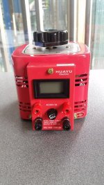
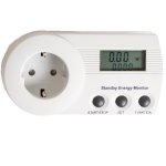
And again: Get a variable voltage transformer. Some Variacs have a current indicator. If not, use a current meter that you insert into the circuit using a test socket. Or attach a clamp meter to an accessible single wire of the AC power supply. Even a cheap energy monitor can do that job...
Then set the output voltage to zero volts, turn on the amplifier, and then slowly increase the supply voltage. While doing so, monitor the current the amplifier draws. And ideally, also the voltages at the quiescent current measurement points. If anything goes wrong, you can intervene immediately before further damage occurs!
So-called "light bulb testers" are just cheap crutches, not suitable for professional use.


That cheap crutches would have prevented failure.
I've seen plenty of professionals use DBTs.
This issue was entirely my own doing, from start to finish. But my new outputs and bits arrive today (Farnell dispatched on a Sunday and it's out for delivery today?! Amazing) so all should be well soon.
This issue was entirely my own doing, from start to finish. But my new outputs and bits arrive today (Farnell dispatched on a Sunday and it's out for delivery today?! Amazing) so all should be well soon.
Of course I mean that you know of the existence of light bulb testers but nevertheless did not use one.
I don't either but have had the luck/experience/OCD like triple checking that stuff nearly* always worked straight away without issues.
*as in "forgotten the failures" 🙂
I don't either but have had the luck/experience/OCD like triple checking that stuff nearly* always worked straight away without issues.
*as in "forgotten the failures" 🙂
Last edited:
Yes, that may be the case, but a variac is clearly preferable to a light bulb tester because you can continuously increase the voltage. They also don't have to be expensive (about 100 euros for a 1000VA model).That cheap crutches would have prevented failure.
Without proper tools, it's better not to even start. You can see the consequences here.
Never had either a light bulb tester nor a variac for the hobby and will probably not ever need either of those. To be clear: I worked as a repair guy with all that stuff available.
I rather have the knowledge and less tools than vice versa 😀
I rather have the knowledge and less tools than vice versa 😀
It´s much better to have both...😛I rather have the knowledge and less tools than vice versa 😀
No reasonable person would ever doubt the benefits of a variable transformer for repairs.
However, specialized workshops use variable transformers with safe isolation, not just simple variacs.
It would be downright negligent to simply connect a device in an unknown condition to the full supply voltage.
For experts and laypeople alike.
It works! Output transistors have all been replaced with modern replacements and the bias temperature compensation has been adjusted per this thread: https://www.diyaudio.com/community/threads/sony-ta-f770es-output-replacement.364196/post-7994405
Bias is set to 35mV on both channels and appears stable even when it gets warm.
DC offset is around 0.9mV on both channels. The adjustment pot isn't precise enough to get it any lower so I decided that was as good as I was going to get!
It's currently playing music beautifully.
@Depaj again I must thank you so much for your help with this. I really owe you. Just one question; I accidentally ordered non-polarised 4.7uF capacitors 🤦♂️so I missed this step out - did you notice that these were particularly necessary, or just a 'nice to have'? If so, I will find some polarised caps.
That's great news !! If I remember correctly they were put in because I had some ringing on square waves, this reduced it a fair amount. Non-polar if good quality should work just fine there. If you have a signal generator, oscilloscope and a dummy load you can test it at high frequencies and check that it stays stable because you probably won't be able to tell just by listening to it.
- Home
- Amplifiers
- Solid State
- I've killed my Sony TA-F770ES by starting a recap (yes, I know) and I would dearly love some help