Just bought a secondhand Chinese 18w valve guitar amp (Schematic attached.)
There's some hum evident with everything turned down (master volume)...I reckon it's 100Hz...which suggests hum on the rail is spewing into the signal path.
I'm no expert wrt valve amps, but 47uf doesn't seem like a whole lot of capacitance for the output stage rail?
So I was thinking about beefing it up to 220uf? (or even more)
thoughts?
Attachments
Last edited:
47uf doesn't seem like a whole lot of capacitance for the output stage rail?
I was thinking about beefing it up to 220uf?
A 47uF input cap is a typical size there. You could add a 10R 10W resistor and another 47uF capacitor
before that point to make a pi filter, which would have about 20dB less hum, probably better than
just adding another 47uF cap in parallel. Too much capacitance right after the diodes could damage
a diode or blow the fuse.
Attachments
Thanks ...all good points.
Any win from dropping a choke into the circuit (or more to the point - any issues doing this?)
Any win from dropping a choke into the circuit (or more to the point - any issues doing this?)
Last edited:
I don't but since it hums even with master volume set to '0' (therefore all signal shunted to ground just before V2B, the hum must either be being generated from V2B (or ripple spewing into the signal from the PSU rail) ...I was therefore thinking about dropping V1 into V2's socket....this should remove the possibility of valve V2 being the cause (unless V1 is faulty too!)
On a similar guitar amp I replaced the 47uF filter capacitors with 82uF and I added a choke. No hum anymore. The choke made a big difference.
As expected. However, depending on where you added that choke, it could have changed operating voltage substantially.
The best of the best (for a passive component upgrade) is a CLC “pi” filter mod. The first C captures the full-wave rectifier peaks; the L squashes all the high frequency business like a boss. The 2nd C further acts to squash hum and tighten up the reservoir (lowering impedance) to the pair of EL84s as this amplifier's output stage.
CRC is fine too. Just don't drop more than about 20 volts of supply (5% of 400 volts), nominally. This of course will require taking a measurement of the quiescent current flow. Can't calculate a resistor without it. A 10 Ω “current sense” resistor in series with things is a good way to get a simple voltage measurement without changing supply-to-circuit voltages very much.
100 mA will show 1 V. Easily in range of inexpensive digital meters.
Good Luck
GoatGuy
While improving power supply filtration (clc or crc) will reduce the hum, i find in a lot of push pull tube amps any mismatch in the output stage will create hum. The output transformer should cancel any hum caused at the output tubes. It could be the tubes are not well matched or the transformer has uneven primary taps.
So, you could really decrease noise by using matched output tubes, adding individual bias for each tube, and adding the aforementioned extra filtration.
So, you could really decrease noise by using matched output tubes, adding individual bias for each tube, and adding the aforementioned extra filtration.
This of course will require taking a measurement of the quiescent current flow.
Would I not need to cater for max current flow? (vs. quiescent).
Given the amp is 18W output (into 8 Ohms) with a rail of 325V .... how could I establish a ballpark spec for a choke that I could drop in situ?
.... how could I establish a ballpark spec for a choke that I could drop in situ?
Read the EL84 datasheet?
You are planning lots of changes without even knowing where the hum is coming from.
You need to determine if the hum is 100Hz or 50Hz, don't just assume.
Let the choke idea sit until you solve the problem.
The hum remains with volume control at zero. SO pull V2, does the hum stop or continue?
It is normal for there to be several volts of ripple on C29, the first filter. IN a push pull amp, the power tubes cancel out that ripple. By the screen node, C30, there should be very little ripple.
That cancel thing? If one side of the push pull stage is not working or if they are seriously unbalanced, it no longer cancels. That is a common cause of hum. A open screen resistor would turn off its power tube, and that would leave the amp unbalanced. Adding filter caps or a choke wouldn't change that. You need to check that both tubes are pulling similar currents.
Has the amp always hummed? Or is this a change from previous operation? Weak filter caps can cause hum,. but so can poor ground arrangements.
Remember, hum is not generic, adding filter caps and chokes won't cure ground related hum, and shielding cables will do nothing for weak filters.
Thanks for all your contributions.
The reason I'm trying to narrow down before even getting my hands dirty, is I don't have much space & I know that once I dismantle it, it'll lie around (eliminating the hum is just one of the things to be done, I wish to have a switch to bypasss the tl-072 at the front of the amp ...which ought to result in a less gainy signal - hopefully cleaner out of the speaker ...plus it means I have an all valve amp for the signal path (!) )....& I really don't want it lying around opened up too long (for a start my wife will get tetchy).
In answer to some of the other questions...
Yes guitar amps hum...but mine needn't - this isn't for live gigs, but will be played in a quiet room at modest levels...I'd rather not hear the hum.
I don't know whether it used to hum (therefore whether this is degradation or not) ....I've only just purchased it.
I'm pretty sure it's 100hz.
Placing the Inductor (if I go that way) further along the power line (towards the preamp - between the first large electrolytic & the secon g 'preamp' electrolytic), will not address the hum I'm currently hearing ...as I say when I turn fdown the ,aster bol...the hum is still evident, so the hum is getting into things from V2B onwards.
If you have bad hum with the Master Volume at 0 then the power amp is the place to look.
I would suspect badly unmatched EL84 output tubes.
My 1st mod would be to add 10 Ohm resistors in the cathode to 0V link for both output tubes so you can check idle currents for corrrect value and near equal idle currents.
Idle currents should be about 28 - 30 mA which would give 280 to 300mV across 10 Ohm monitoring resistors.
You might just need a new matched pair of EL84.
Of course if it is new and really bad you should explore your warranty options before doing anything.
Cheers,
Ian
Hi Ian....thanks for your suggestion (the amp is way out of warranty)
RE the current measurement ...rather than start inserting resistors, couldn't I just measure the DC resistance of the OT primary windings (i.e. each side to the centre tap) & the associated voltage drop across each winding ..then it's a simple case of I=V/R
RE the current measurement ...rather than start inserting resistors, couldn't I just measure the DC resistance of the OT primary windings (i.e. each side to the centre tap) & the associated voltage drop across each winding ..then it's a simple case of I=V/R
Last edited:
...couldn't I just measure the DC resistance of the OT primary windings (i.e. each side to the centre tap) & the associated voltage drop across each winding ..
_I_ believe it is un-safe to work with both meter-leads at 300V.
(And trying to sense 303V from 302V becomes small differences of large values and is poor accuracy.)
A few-Ohm cathode resistor is much safer. For you and the amp.
But if you have not had enough shocks through your body, or need to practice B+ repairs, go ahead and poke the OT.
All fair points.
That said, from my multimeter's perspective, I see little difference between placing my Multimeter's -ve probe to ground & the +ve probe to B+ (325V) ..... versus measuring across the OT's primary coil tap - I'm measuring potential difference & indeed the potential difference is much (much) lower for the latter scenario (& I'm not trying to trap/differentiate 302V from 303V ...I'm measuting the potential difference across the coil ... 1V ...should be measured failry accuratel). Placing a resistor in circuit involves being invasive to the current wiring (to get a resistor in series)
About 30yrs ago I worked for the British Royal Air Force as a Radar engineer (admittedly I'm a little rusty nowadays!)...at the time it was mainly valve equipment...so I've had my fair share of -500V DC shocks (on my knees reaching at length into console equipment to try & measure DC voltages ensured plenty of glimpsing - but wake you up - shocks).
Therefore a B+ of 325V by comparison doesn't faze me ...it'll be nostalgic ...afterwards, I shall wear some flares & slip Dark Side of the Moon on my LP player ;-)
Last edited:
You can indeed measurer DC resistance of the 2 half primaries of the Output Tranny and then calculate idle currents from the voltage drops across each. I have done this on some commercial amps with PCBs and no cathode current monitoring resistors.
People like PRR and I do not usually suggest it and in fact discourage it, as we have no way of knowing if the the level of experience AND training of the poster is up to that task.
In modern times in the day job, every task has to have a risk assessment done, then an analysis done of ways to eliminate or mitigate risk, etc. We would have to conclude (in this case) that there is a less risky way. The old "suitably trained personnel" can do it just doesn't fly with the OH&S people.
Cheers,
Ian
Ok, curiosity got the better of me....
Removing V2 made no difference to the hum (the 12ax7wa are sovtek .would the 0403 at the foot of the printed text on the valve refer to April 2003 manufacture date?)
The EL84EH are electro harmonix (0510 at the bottom of the printed text ...May 2010?)
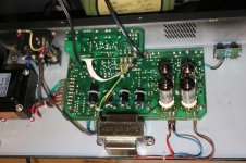
V3 anode circuit ... 3.05V DC measured across the OT primary coil tap (blue/red wires) .... it was solid/static reading (coil tap measures 92.6 Ohms with V3 removed from circuit) , therefore 33mA quiescent
V4 anode circuit (valve removed from circuit) ... 1.19V DC measured across the OT primary coil tap (brown/red wires) ....the reading was jittery +/- 100mV (coil tap measures 118.4 Ohms with V4 removed from circuit), therefore 10mA quiescent
That's a whopping disparity between the OT primary winding coiltap resistances (but then again, I've no depth experience with output transformers)....so, looking at those results, I would say I probably need a new output transformer - any thoughts?
Here's a piccie of the internals (as I couldn't find one on the internet anywhere for this particular amp)
Removing V2 made no difference to the hum (the 12ax7wa are sovtek .would the 0403 at the foot of the printed text on the valve refer to April 2003 manufacture date?)
The EL84EH are electro harmonix (0510 at the bottom of the printed text ...May 2010?)
V3 anode circuit ... 3.05V DC measured across the OT primary coil tap (blue/red wires) .... it was solid/static reading (coil tap measures 92.6 Ohms with V3 removed from circuit) , therefore 33mA quiescent
V4 anode circuit (valve removed from circuit) ... 1.19V DC measured across the OT primary coil tap (brown/red wires) ....the reading was jittery +/- 100mV (coil tap measures 118.4 Ohms with V4 removed from circuit), therefore 10mA quiescent
That's a whopping disparity between the OT primary winding coiltap resistances (but then again, I've no depth experience with output transformers)....so, looking at those results, I would say I probably need a new output transformer - any thoughts?
Here's a piccie of the internals (as I couldn't find one on the internet anywhere for this particular amp)
Attachments
Last edited:
- Status
- Not open for further replies.
- Home
- Live Sound
- Instruments and Amps
- I've got Hum-age... not happy