Kinda' noob question:
Is it correct to see the DAC output Z (670R) forming a voltage divider with the IV stage input Z?
If true then obviously an IV with a flat input Z from DC up to 10MHz of say 3R (I forgot to check but it is probably close to what Hawksford proposes - have to check...) will display less noise at its output than an IV with 10R of input Z.
May I conclude that when evaluating the two approaches: Jocko (OL) or Hawskford (CL) vs. opamp IV then measuring noise over a wide band should be one of the criteria? 😕 I agree that slew rate limiting is also an issue, especially with poorly chosen OpAmps.
Tks!
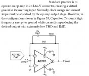
I tried this around 1991 or so, the DAC is probably out of date now. The two capacitors and the BW of the op-amp form a critically damped two pole system, I don't know about the Dutch circuit but the principle is similar. The results at the time were remarkably good. The picture is from 797 datasheet🙂
Attachments
Joseph K said:Hm, I was asking because in the hawksford model 1nF of Cfeedback is also included, with 1mA Dac output current, and 50V/usec slew rate for the opamp. Which is more than twice the 20V/usec for the OPA134.
And he got well visible spuries at 44.1KHz.. A test would well respond to any doubt here..
Given that Tentlabs offers that NOS filter replacement unit developed by Peter Beyer, so it should be a no pain quick test.. and also interesting for the possible users.
George, you mean 48 kHz in fig.3-8a of Hawksford, but that is mutch worse than 3-10a which corresponds about with 8x oversampling, if I'm right.
Is this true? With the 1800 pF in parallel the gain has been lowered with 40 dB at 3.5 MHz. From 0 - 20 kHz the signal could be 8.8Vpp (with 0 dB on disk) indeed, but not at higher frequencies. Do I make a mistake?Joseph K said:Again, uhm, let's try to re-calculate the slew rate requisites for the OPA:
The maximum swing Ipp for the PCM63 is 4mA. That is converted by the 2.2Kohm in your converter to 8.8Vpp max. - on the OUTPUT.
That is, this is the step which should be re-created by the opamp on it's output..
With OS is mutch better (see above), right? I still have somewere a wrong exchange of ideas. The 4 mA jumps are in both cases 200 ns, so....... what is the difference for the slew rate?................help!Now this is extreme, but it's how it looks your 20KHz +19KHz test signal without OS!

I think so, yes.sidiy said:Kinda' noob question:
Is it correct to see the DAC output Z (670R) forming a voltage divider with the IV stage input Z?
If you had watched my attachments a little bit more careful, you could have noticed that the input Z is under 20 kHz mutch smaller than your 3 ohm.If true then obviously an IV with a flat input Z from DC up to 10MHz of say 3R (I forgot to check but it is probably close to what Hawksford proposes - have to check...) will display less noise at its output than an IV with 10R of input Z.

No, you may not because in my case the audible noise is more than 30 dB less.😡May I conclude that when evaluating the two approaches: Jocko (OL) or Hawskford (CL) vs. opamp IV then measuring noise over a wide band should be one of the criteria?
While an opamp can be okay, you should at least try a dedicated I/V converter before condemn it.
Measured input impedance.....
With a PM3233 oscilloscope (10 MHz, 35 ns, 2 mV/cm) and a decent probe, I measured the output voltage over the pins 6 and 7 of the PCM63 (which is followed by my op amp IV with OPA314).
I could see LF-signals from a few hundred Hz up to 20 kHz. The higher the frequency the larger the signal,
BUT,
I could not find anything at 8 x fs which is about 3.5 MHz. NOTHING. Even without the 5 nF capacitor!
I think, I cannot trust my simulations. The IV is much better than expected from simulation.
I think I leave out the 5 nF either.
Later I will measure with W&G's PSM5 to see how small the recidues are at 3.5, 7, 10.5.... MHz.
janneman said:BTW Herbert your website has lots of interesting ideas! Thanks,
Jan Didden
Jij kan die lezen, ja....
Bedankt voor de bloemen.
PA0SU said:With OS is mutch better (see above), right? I still have somewere a wrong exchange of ideas. The 4 mA jumps are in both cases 200 ns, so....... what is the difference for the slew rate?................help!
I did find the answer myself!
From my radio-experience I know that in a heterodyne receiver a small distance between local oscillator (LO) and the frequencies to be received (RF) gives a lot of spurious. In general: the larger the distance, the less spurious. However there are regions you should better not use (see my web site).
In this case the RF is the audio-band ( 10-20,000 Hz) and the LO is the sampling rate..........
In our case the 'mixer' is the IV-conv. This should be very linear so that the spurious are as small as possible of course, but oversampling is a must from this point of view.
(I never understood the non oversampling lovers.......)
PCM1704 iso PCM63
With a PCM1704 one will find less intermod distortion than with a PCM63 because the 1704 outputs 1.2 mA and the 63: 2.0 mA!
Perhaps folks think the 1704 is a better DAC than the 63 because 'thay sould better'.
It could very well be that their IV-conv can't handle the 2.0 mA from the 63!!!
With a PCM1704 one will find less intermod distortion than with a PCM63 because the 1704 outputs 1.2 mA and the 63: 2.0 mA!
Perhaps folks think the 1704 is a better DAC than the 63 because 'thay sould better'.
It could very well be that their IV-conv can't handle the 2.0 mA from the 63!!!
OPA 134 in stead of OPA 314
Sometimes I typed OPA314 in stead of OPA134. This could give some problems.
I apologize myself.....
Sometimes I typed OPA314 in stead of OPA134. This could give some problems.
I apologize myself.....
Last weeks I did some investigations on I/V-converters with op amps.
Look at my website under: I/V-converters (for CD-players)
Look at my website under: I/V-converters (for CD-players)
Congratulations! Very nice work.
For OPA648 and similar op-amps there's an article on Walt Jung website : http://waltjung.org/PDFs/High_Performance_Audio_Stages_Using_TransZ_Amps.pdf The trick discussed there may help to reduce the distorsions.
For OPA648 and similar op-amps there's an article on Walt Jung website : http://waltjung.org/PDFs/High_Performance_Audio_Stages_Using_TransZ_Amps.pdf The trick discussed there may help to reduce the distorsions.
- Status
- Not open for further replies.
- Home
- Source & Line
- Digital Line Level
- IV-convertor with op amps....