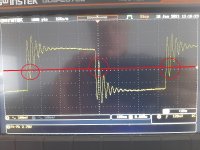
It looks rather awful. How did you connect the oscilloscope probe ground? Straight at the S/PDIF output ground or via some big detour? Is the required 75 ohm S/PDIF termination resistor in place?
Terrible waveform.
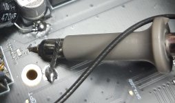
Make sure you use a 10x scope probe with the short ground spring on it, not the alligator clip ground lead. The inductance of the clip wire turns any signal with even moderately fast edges into a mess. Then, probe the SPDIF RCA output. If the scope tip is too short to reach inside the RCA, you can stick a male RCA connector in to get a better probing point. The important thing is the scope ground spring should be on the RCA ground, not somewhere else, and especially not with the alligator clip on the chassis.
Do not use a 1x scope probe.
If you use a RCA to BNC coax to plug the scope directly, and even if you use a 75R coax to match the output impedance, the scope doesn't have a 75R termination. It's simpler to just use a good x10 probe.
Last edited:
That is directly at the chip inside of the DAC. The probe x10 of course.
Attachments
Last edited:
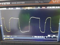
There should be a probe calibrator on the front of the scope, it should deliver a clean square wave...
btw, your scope probably came with 2 probes?
btw, your scope probably came with 2 probes?
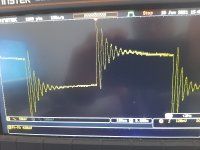
The waveform is perfect with the oscilloscope calibrator. The most likely there is a resonance between capacitance of a probe and inductance. The probe has 60Mhz bandwidth at 10x and the oscilloscope has a 70Mhz bandwidth. Tomorror I'll put a series 200 ohm resistor to damp this oscillation. Or maybe the oscilloscope bandwidth is too small for that step signal.
Yes, my scope has 2 probes. It is a GWInstek GDS-2072E
Yes, my scope has 2 probes. It is a GWInstek GDS-2072E
Last edited:
This looks better, but for that sort of signal probed on a PCB it's weird that it's showing transmission line reflection artifacts (they're the little wiggles on the edges)...
but the problem is... can you really trust these probes?
but the problem is... can you really trust these probes?
For that high fronts, high dv/dt, the most probably the scope and the probes are out of range. I want to buy a 300Mhz scope with 500Mhz probes from Rigol. It will be enough to see correct S/PDIF signal ?
Yeah, sure. I've got a DS2072 with the software hack to enable 300MHz bandwidth. It works well. The newer models are most likely even better.
Although a low bandwidth probe should just limit the bandwidth and slow down the edges, it shouldn't ring or show other weird effects...
Although a low bandwidth probe should just limit the bandwidth and slow down the edges, it shouldn't ring or show other weird effects...
60 MHz should also be enough for S/PDIF and like peufeu wrote, a too small scope bandwidth would make the waveforms smoother, not cause excessive ringing.
I put a series resistance of 240ohm and nothing has changed. Is the ground missing the truth culprit ?
- Home
- Source & Line
- Digital Source
- It's this S/PDIF signal OK?