The old classic it worked before the recap! I made the mistake of not checking the polarity of the capacitors and installed C19 backwards 🙁. Its been on a dim bulb since the recap not full mains but alas somethings not right and I just cannot find the fault.
The amp seems to work when the tone controls are switched into the circuit, When they are switched off the amp faults and the relay chatters along with itself for a minute or so then stops with the relay open i.e in protection.
Any ideas what I could have damaged? any of the IC's?
The amp seems to work when the tone controls are switched into the circuit, When they are switched off the amp faults and the relay chatters along with itself for a minute or so then stops with the relay open i.e in protection.
Any ideas what I could have damaged? any of the IC's?
Attachments
Check for lifted pads where you removed the caps (check continuity between the cap leg and the circuit trace). Check other caps for polarity.
Sometimes the pads look good but do non connect after capacitor removal.
Sometimes the pads look good but do non connect after capacitor removal.
Especially check the connections of traces/pads/vias on top of the board, under the capacitors.
These would be more likely to be damaged when removing the old caps than those on the bottom.
A via can get pulled out of the hole along with the lead, and you might not have noticed.
A short of C19 should not have done real damage. I would check elsewhere you have been in the circuit.
These would be more likely to be damaged when removing the old caps than those on the bottom.
A via can get pulled out of the hole along with the lead, and you might not have noticed.
A short of C19 should not have done real damage. I would check elsewhere you have been in the circuit.
Last edited:
Is it possibly an anomaly of this particular amp + DBT and that there isn't really a problem at all?
Especially check the connections of traces/pads/vias on top of the board, under the capacitors.
These would be more likely to be damaged when removing the old caps than those on the bottom.
A via can get pulled out of the hole along with the lead, and you might not have noticed.
A short of C19 should not have done real damage. I would check elsewhere you have been in the circuit.
I'll check the soldering again along with the caps, see I've missed anything.
Its only a single sided board so no issues with through plating being damaged.
Is it possibly an anomaly of this particular amp + DBT and that there isn't really a problem at all?
It has been on a dbt before with no ill effects.
The amp in question is a kenwood ka-1000
Fair enough 🙂
If it works with the tone controls in circuit then it should be possible to see what has gone amiss. Given that the controls are in the feedback loop it is possible that perhaps a wrong value cap has been fitted and that is sending it into instability. Worth checking polarities by voltage measurement as well as sometimes board layouts and manuals can have errors.
If it works with the tone controls in circuit then it should be possible to see what has gone amiss. Given that the controls are in the feedback loop it is possible that perhaps a wrong value cap has been fitted and that is sending it into instability. Worth checking polarities by voltage measurement as well as sometimes board layouts and manuals can have errors.
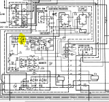
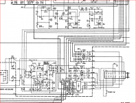
I've given it a good look and the caps are the correct value and are the correct way around. I've started to take voltage measurements board by board and have come across a 12v zener (D4) that measures 9v, defective zener or something else? I've attached the relevant part of the schematic.
Attachments
Those look like they are used as simple shunt regulators and so the voltage might be low simply because there isn't enough raw supply (because of the DBT). Obviously check it out but I'll bet the Zener is fine.
That's what I thought they were, just questioning as the negative 12v zener reads OK.
Just had a few minutes to check and realised that when touching a components in the right channel with the meter (when tone controls are on) makes the relay open, take it off relay closes.
Just had a few minutes to check and realised that when touching a components in the right channel with the meter (when tone controls are on) makes the relay open, take it off relay closes.
It sounds like you done something amiss and are just not seeing it.
Could a trace be broken around one of the pads of a cap and so the amp is going unstable due to an open feedback loop somewhere. That kind of thing is so easy to do and goes unnoticed.
Could a trace be broken around one of the pads of a cap and so the amp is going unstable due to an open feedback loop somewhere. That kind of thing is so easy to do and goes unnoticed.
I've given it a good look and the caps are the correct value and are the correct way around. I've started to take voltage measurements board by board and have come across a 12v zener (D4) that measures 9v, defective zener or something else? I've attached the relevant part of the schematic.
Try working backwards.
Check the relay is making proper contact with the pcb and then work back from the relay driver and tone control switch checking voltages in the manual at various points and checking Vbe of transistors.
I had a chattering relay in a Technics receiver amplifier. I found pressing the pcb gently near the coil connections got it working. The relay used to engage with an audible click. It was a heavy duty type and I believe when there is a click there is some mechnical shock on the pcb which manifested itself over the life of the receiver - which dates from the 1990's.
I've checked the orientation, values, pads on the work that has been done and they all check out ok. With the tone controls in circuit it passes a wave and works perfectly. Vbe seems ok, just slight suspect on q32/34 as Vbe is 7.2v but amp works normally under certain conditions. This is getting frustrating!
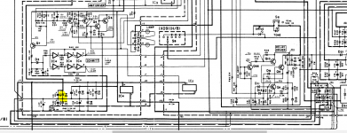
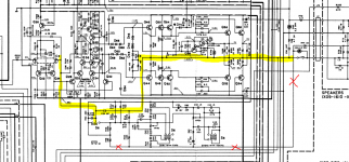
As its been a while since learning this can anyone check the schematic I've posted where I think I've highlighted the feedback loop in yellow, also the part with the red crosses is this part of the loop? If not what does this do? Also when the tone controls are switched off what does this switch into the circuit?
As its been a while since learning this can anyone check the schematic I've posted where I think I've highlighted the feedback loop in yellow, also the part with the red crosses is this part of the loop? If not what does this do? Also when the tone controls are switched off what does this switch into the circuit?
Attachments
According to the schematic posted the voltage at the emitters of of Q32 and Q34 is 6.4 V. You should check that as 7.2V vbe is out of line with base to emitter diode voltage which should be around 0.6V
Q28 and Q30 set the base voltages for the above transistors. The value for those is shown on the schematic next to Q22 but the figure is indistinct.
Q28 and Q30 set the base voltages for the above transistors. The value for those is shown on the schematic next to Q22 but the figure is indistinct.
The part you highlighted is just an 8pF (is it 8?) compensation cap that is permanently connected.
The feedback proper is in parallel to that cap and via the whole network below it which is the tone control circuit and its switchable turnover frequencies.
When you switch the tone control out of circuit you retain the path you marked in red which then connects via that lower left resistor feeding into the left hand SW6 switch.
I've checked the orientation, values, pads on the work that has been done and they all check out ok. With the tone controls in circuit it passes a wave and works perfectly. Vbe seems ok, just slight suspect on q32/34 as Vbe is 7.2v but amp works normally under certain conditions. This is getting frustrating!
As its been a while since learning this can anyone check the schematic I've posted where I think I've highlighted the feedback loop in yellow, also the part with the red crosses is this part of the loop? If not what does this do? Also when the tone controls are switched off what does this switch into the circuit?
The tone control section would be in the nfb decoupling arm to earth. There should be a switchable RC divider that substitutes for the tone control decoupling arm.
To find this I suggest you copy the pages and adapt the scale any so interlinking horizontal lines between these align closely enough to follow. I have done this before and taped my pages together.
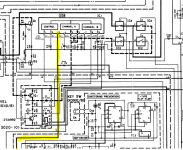
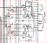
I have looked up a Service Manual for this as the result of comments in another thread for a Kenwood M2 which has a Sigma servo circuit and see the KA1000 has this same feature. If the Sigma cord is mis-connected this activates a protection circuit shown in Fig.2 on page 3. the screen frame shot shows the area on the schematic where you might check connections to see if this is your problem.
It is possible the Sigma signal sense terminals have only one connection such that you get jagged results if there is no connection but this changes to something approaching normal due to the signal connection from the Sigma servo when a speaker is connected.
It is possible the Sigma signal sense terminals have only one connection such that you get jagged results if there is no connection but this changes to something approaching normal due to the signal connection from the Sigma servo when a speaker is connected.
Attachments

Back to this now.
The sigma drive components check out fine, the problem dosent seem to be there. As mentioned before in channel A where i think the fault lies. If I take any multimeter lead and touch components up to where I have tested to q44/46 this faults the amplifier with something pulling too much current, take the probe off and the fault disappears what would cause this? Instability, lost ground?
Also how would I separate the pre from power on this so I can eliminate things?
Can't see the preamp having anything to do with it tbh but it is easy to separate. You should be able to remove R202 which feeds the gate of the first FET.
I imagine that goes to the volume control but in any case just lifting the resistor isolates the power amp from the preamp section. The amp should be stable in that state but will be extremely sensitive to stray pickup so do not touch the gate or components connected to the gate when testing.
Another option is to apply a short from the left hand end of R202 to ground. That shorts the preamp section feed and prevents any interaction.
What you describe around Q44/46 suggest the amp is unstable and the slight capacitance/ pickup from the meter leads is sending it crazy.
You have to go back to your original statement of 'It worked before the recap' 🙂 and don't get side tracked into weird and wonderful scenarios.
It's something you have done.
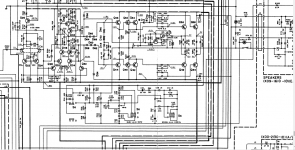
The tone control switch has a gang that connects to the relay control circuitry There is a pair of 2u2 bypass capacitors across the contacts.
Q66 and Q10 appear to lead to the headphones suggesting these deactivate the relay when the jack is inserted in the socket.
Furthermore there are 2u2 capacitors C59 and C60 on the live side of the relay for each channel with connections between the sensor and normal output terminals positive and negative for each respectively.
If any of these are not are not making proper contact the offset change in balance between Q85 and Q86 then the effect via R365 to the base of Q66 would cause the relay to drop out.
Attachments
- Home
- Amplifiers
- Solid State
- It worked before the recap