Hi,
I have some issues with my Musical fidelity A1 (2008 version). when I turned on, I have no sound at all from all entries. when I opened the amplifier, I saw 2 relays. Only one seems to be ok. Do you know how can I test them? (i am french, apologize for my english language).
thanks in advance fpr your help.
If you suspect one isn't operating (and you want to test it in circuit without removal) then the first thing to do would be to measure the voltage across the coil part of the relay in order to confirm that it is actually being powered.
If the correct voltage is present then the contacts that are supposed to close should do so. That can then be checked initially by confirming that no voltage is present across the supposed closed section and then only if that is OK can you then back that up with a simple resistance check for continuity across the contacts.
A two minute job 😉
(I'm assuming these relays are all on the low voltage side of things. If they are on the mains side then you must exercise extreme caution when testing)
Your English is fine 🙂
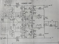
I have got an old A1 device (MK-I - i. e. two heat sinks on the top) from this model to work out steps for enhanced sound quality. By study the schemas from the web I discover some missprints concerning polarity of caps at the power amp section.
there are follow missprints for polarity at the schema under
Mark's Pages › Image Viewer
C10 and C13 (NFB)
and there are follow missprints for polarity at the schema under
Anyone spot the BIG problem with this? - Page 10 - pink fish media
C10, C14 and C13 (NFB)
Is my estimate right?
I will report next time the real live polarity of this components at my own A1 device.
To this model I have additional questions - go therefore to
http://www.diyaudio.com/forums/solid-state/63629-anyone-know-musical-fidelity-a1-x-amplifier-2.html
for saving against delete I have upload the (by URL mentioned) jpg pictures of both schematic versions
Attachments

Last edited:
It is not difficult to see what the correct orientation of the capacitors is, although the actual voltages are so small it almost does not matter.
First, TR1 and TR2 have the base current flowing out of the bases and into ground through 1k and 47k, making the input side of 47k slightly positive. Therefore, the input and feedbacl caps to the bases of TR1/TR3 should have their plus terminal connected to the bases.
For TR3 and 4 the situation is reversed, so it's the minus terminals to the bases.
Note that the inclusion of the offset voltage on the feedback side does NOT change this as the whole point of the amplifier is to balance out this offset by the voltage drop on 0R22 output resistors, therefore establishing a standing current in the output stage.
Also, since TR2 base is slightly positive and TR4 base is slightly negative, C10 is the only one in these schematics that is correctly polarized.
The bias current in the output stage can be varied either by changing the 0R22 resistors or R11/R6. Imbalance of the beta in the TR1/2 and TR3/4 pair leads to output offset, and beta as such figures a lot in what exact bias current will result as the input impedance of the differential stages is not very high. Choosing high beta transistors for TR1..4 makes things much more predictable - assuming (and this is important!) the same voltage on both 12V zener diodes (these are also used to supply the preamp, from one output channel, therefore the dual values on the series resistors to the zeners).
It is also possible to redesign the stages so that the input bases can be connected directly, therefore canceling much of the bias current. It is also possible (and desirable) to replace the input caps with small foil caps (or cap, in case of the bases being connected). The feedback side can also be redesigned for simpler setting and in fact adjustable DC offset and bias currrent.
- Status
- Not open for further replies.