Hi all!
Sorry for my first post being one with a load of questions 🙂
I’m not very adept at the nomenclature concerning electronics, as this is my very first project, so my apologies if some of the labeling goes awry.
I'm currently trying to make a CMOY style headphone amp for a eurorack system (synthesizer environment ) on a NJM4556 op-amp basis, the reason being, that op-amp should be able to drive a wide range of headphones. I started out with the NE 5532 D but I’ve read in a post that wouldn’t be able to drive much and I couldn’t make it work properly.
Eurorack also means that I cannot deviate from a 12 volt power supply and I need to reduce the input signal from 5 volt peak to peak to 2 volt peak to peak, as I want eventually to make this into a module to rig into my current eurorack system.
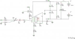
Included you’ll find a schematic (yes with fritzing, I know 😉 ) of one channel ( I have made both left and right though) of where I’m currently at, I’ve cobbled this together from various designs I found for CMOY’s on DIYaudio concerning the NJM4556 and virtual ground designs, but I do run into some issues;
I’m not amplifying at all, if anything, as soon as I switch on power, the output seems to reduce itself considerably and randomly distort. I also experience phasing in the output. The headphone I try to drive is a Beyerdynamic custom studio with a impedance of 80 ohm. But I would like it to work with headphones ranging from 32 to 250 ohm.
If I solder in the headphone jack after the “voltage reducer” (the resistors before the 10k pot) it sounds fine(ish) for something that drives directly from the synthesizer.
Hopefully I’ve made a blatant oversight which is easy to point out. Thank you for reading!
Sorry for my first post being one with a load of questions 🙂
I’m not very adept at the nomenclature concerning electronics, as this is my very first project, so my apologies if some of the labeling goes awry.
I'm currently trying to make a CMOY style headphone amp for a eurorack system (synthesizer environment ) on a NJM4556 op-amp basis, the reason being, that op-amp should be able to drive a wide range of headphones. I started out with the NE 5532 D but I’ve read in a post that wouldn’t be able to drive much and I couldn’t make it work properly.
Eurorack also means that I cannot deviate from a 12 volt power supply and I need to reduce the input signal from 5 volt peak to peak to 2 volt peak to peak, as I want eventually to make this into a module to rig into my current eurorack system.
Included you’ll find a schematic (yes with fritzing, I know 😉 ) of one channel ( I have made both left and right though) of where I’m currently at, I’ve cobbled this together from various designs I found for CMOY’s on DIYaudio concerning the NJM4556 and virtual ground designs, but I do run into some issues;
I’m not amplifying at all, if anything, as soon as I switch on power, the output seems to reduce itself considerably and randomly distort. I also experience phasing in the output. The headphone I try to drive is a Beyerdynamic custom studio with a impedance of 80 ohm. But I would like it to work with headphones ranging from 32 to 250 ohm.
If I solder in the headphone jack after the “voltage reducer” (the resistors before the 10k pot) it sounds fine(ish) for something that drives directly from the synthesizer.
Hopefully I’ve made a blatant oversight which is easy to point out. Thank you for reading!
Attachments
Hi, congratulation with first project!
I see few mistakes in your schematic.
But in the beginning one important question (I have no idea how eurorack system is build) : have your audio source (sinthesizer?) use the same 12V power, you use for your CMoy? If so, is your sinthesizer's output's ground common with -12V ? If your source ground is -12V, you can't use traditional CMoy with virtual ground.
now about mistakes, I see in schematic:
volume pot is connected wrong way. Contact 2 must be to ground, contact 3 (with arrow) go to input cap C1, R6 and R1 drop out.
-6,15V connect to chip negative power leg 4
C5, C2, R8 drop out, headphone direct to output leg 7
you can replace R3 andR7 with one resistor
About chip choice - best choice is good quality opamp socket 🙂
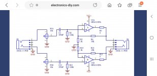
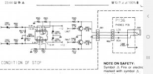
Here's cmoy schematic first picture based on opa2132, and Marantz cd 63 hp schematic(second picture) based on njm4556 with much lower gain.I'd say that if you go with a bipolar op amp it's better that the resistor from pin 2 and pin 6 to ground to be decoupled through 100uF capacitor .Njm4556 doesn't really need it as it doesn't have real problems with virtual ground bias either because its bias current is actually lower than the residual leakeage current of a very good wet electrolitic capacitor including nichicon muse bipolars thus the output offset is not significant.With njm4556 you might not even need a bias resistor to ground in pin 5 and pin 3...although it's better to have it.Jfet op amps like opa2132 never need bias if the signal is coupled through electrolitic capacitors.They'll use the cap's leakage current for that.Still...better wisdom is to use one in case you're going to use a low value input film capacitor.
Attachments
@Zigis
Many thanks for your reply! In short; a eurorack system consist of multiple modules from mostly different manufacturers which perform different tasks; filters, audio and control sources etc. And use a shared bipolar 12v DC power bus (+12V, 0V, -12V). So no virtual ground, that’s something really useful to know! It needs to be powered from the same power supply then? I’ve tried my iPod as a source and although there is no amplification it does seem to resolve the distortion and phasing issues. I currently use a separate 12 volt power supply. I’ll make the changes you suggested and update my schematic. I did hook up the volume pot correctly thankfully! 😛
@dreamth also many thanks for reply and the schematics!
Good quality capacitors are low ESR ones, right? I do have the Panasonic M-A 100U 25 Elco, 100 uF, 25 V lying around. I see that the schematic for the Marantz cd 63 uses a much higher value resistor for the gain feedback loop compare to the one I’m currently using; 12k instead of 4,7k. Does that make a big difference in output?
Do you also recommend using the OPA2132PA instead of the Njm4556? Or just to switch them around to see what works best?
Thank you guys for helping me out, I’ll keep you posted!
Opa2132 is better only if you drive 600 ohms loads so you need to know your headphones impedance, the series output resistor, the needed output voltage and the min supply voltage that will allow for enough headroom so that the series ouput resistor allow enough voltage on the headphones.Usually with at least +-12v supply you can safely use 600ohms headphones or 330ohms output series resistors and 250...300ohms headphones or 620 ohms output series resistors and +-15v supply with high SPL 32 ohms headphones but some 32 ohms headphones won't get enough power and better use njm4556 with 150... 68 ohms output resistors for 32...64 ohms headphones.
Then the matter of feedback resistors is a delicate one.Your gain is around 5x, marantz gain is around 2x.They used higher resistor values because the older opamps in general were more sensitive to common mode distortions and one cause for that is the unequal impedance at both inputs.So they wanted to present both inputs similarly high impedances to minimize distortions sacrificing a bit of signal to noise ratio, but njm4556 has quite low bias current and it's not affected too much by the value of those resistors especially with such a low gain.
Then the matter of feedback resistors is a delicate one.Your gain is around 5x, marantz gain is around 2x.They used higher resistor values because the older opamps in general were more sensitive to common mode distortions and one cause for that is the unequal impedance at both inputs.So they wanted to present both inputs similarly high impedances to minimize distortions sacrificing a bit of signal to noise ratio, but njm4556 has quite low bias current and it's not affected too much by the value of those resistors especially with such a low gain.
Last edited: