I had an issue the other day with the heater wiring in my Tubelab SSE amp. I turned the amp on in the morning, and no sound. This was odd because I listened to the amp just the evening prior and was really enjoying it. I noticed that the power tubes and driver tube were not glowing at all. The rectifier was glowing and was getting hot, but the other tubes looked off and were not hot to touch. I then turned the amp off, unplugged it, and flipped it over to see what was going on.
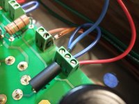
I've attached a picture to this post. The brown wires connecting to the 2 position terminal block are the heaters. You can see that one terminal looks burned or scorched. It looks like the plastic has melted, there's some sort of brown goop on the wire coating, and the screw is stuck but good - I havn't been able to turn that screw. The heat damage is only on the one side of this 2-position block - the other side looks fine.
When I started investigating further, I noticed that wire was not cinched down well in the terminal block. It could be pulled in or out w/o undoing the screw (which in a sense is good because I can't undo the screw...). Could this bad physical connection be the cause of the melted plastic? If so, I'd be grateful if someone would try to explain to me how that works. I've got the board unconnected now to do some modifications to the chassis and to add a big motor run capacitor. When I put it back together, I'll be much more careful with all of the terminal block connections, making sure the wires are all cinched down and snug. I've ordered a new 2-position terminal block, but is there anything else that I should check or be worried about before firing the thing back up?
Thank you all in advance for your help!
Dan
Attachments
A loose connection can heat up from the increased resistance, and if hot enough it could melt
the plastic. Sounds like that's what happened. I would also cut an inch or so off of the wire(s)
that got hot to have fresh contact that isn't oxidized.
the plastic. Sounds like that's what happened. I would also cut an inch or so off of the wire(s)
that got hot to have fresh contact that isn't oxidized.
Last edited:
If I might make a suggestion...those 'screw down' terminal blocks I have have found to be kinda hit or miss. Think about it, you have a somewhat round collection of stranded wires...you're containing them within a tight space & are trying to crush them underneath that set-screw. Since copper is somewhat stiff & strong, you are not really crushing those strands...myself, I tin the wires with solder first, as the set-screw is coming down it easily crushes the solder that is melted thuout the bundle of wires...the surface area is by far greater than bare wires.
--------------------------------------------------------------------------------------------------------------------------------------------------------Rick..............
--------------------------------------------------------------------------------------------------------------------------------------------------------Rick..............
The screws will work loose over time as the individual strands in a stranded wire move. I second the suggestion of tinning the wire with solder before putting it in the terminal.
I have found that the screws need to be re-tightened two or three times on a new amp build before they settle if the wires are not tinned, and maybe once if they were.
In this case I would replace that individual terminal block and reinstall the wires. While inside the amp tighten all the terminal screws. If possible, tinning the wires and reinstalling them will help long term.
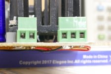
The green terminals that I have incorporate a thick metal strip between the set screw and the wires, so the screw itself is not working on the wire. The square box in the terminals closes upward as the screw is tightened. The wire must go above the metal strip in these terminals. Make sure the screw is fully loosened before inserting the wire. It is possible to place the wire on the wrong side of the lever if the screw is partially or fully tightened before inserting the wire. This WILL lead to a loose connection and lots of frustrating moments with the amp. Always pull test the wire after assembly to verify proper assembly.
I got come cheap blue connectors from a surplus company that did run the screw against the wire. Those came loose often, and even cut a wire or two in half. All eventually went into the trash.
These terminals are not designed to hold two or more wires per connection, especially if they are different gauges. Two identical wires seem to work OK if they were both tinned.
I have found that the screws need to be re-tightened two or three times on a new amp build before they settle if the wires are not tinned, and maybe once if they were.
In this case I would replace that individual terminal block and reinstall the wires. While inside the amp tighten all the terminal screws. If possible, tinning the wires and reinstalling them will help long term.
The green terminals that I have incorporate a thick metal strip between the set screw and the wires, so the screw itself is not working on the wire. The square box in the terminals closes upward as the screw is tightened. The wire must go above the metal strip in these terminals. Make sure the screw is fully loosened before inserting the wire. It is possible to place the wire on the wrong side of the lever if the screw is partially or fully tightened before inserting the wire. This WILL lead to a loose connection and lots of frustrating moments with the amp. Always pull test the wire after assembly to verify proper assembly.
I got come cheap blue connectors from a surplus company that did run the screw against the wire. Those came loose often, and even cut a wire or two in half. All eventually went into the trash.
These terminals are not designed to hold two or more wires per connection, especially if they are different gauges. Two identical wires seem to work OK if they were both tinned.
Attachments
All,
Thank you for the help. I will follow your advice once I get the new terminal block from Mouser.
I can't remember where, but I did read somewhere a while ago advising against tinning wires before securing them in terminal blocks. The logic was that solder continues to "flow" over time, moving along the strands of the wire, and that this can lead to less secure connections. I don't know about the veracity of this logic....
Just out of curiosity, what are the arguments against soldering the wire directly to the wholes in the board? I imagine that doing it the first time is fine and probably provides a good connection, but that subsequent connections are maybe not as secure?
Again, thank you all for your help.
Dan
I have heard arguments both for and against tinning the wires before inserting them in a terminal block. I find that a tinning with a minimal amount of solder works best for me, but I tend to take things apart and mess with them a lot. Too much solder will leave a blob somewhere resulting in uneven diameter and only a small contact area which will compress over time. I use just enough solder to keep the strands from moving under vibration.
There is no problem soldering the wires directly to the board, and I often do that in things that see a lot of vibration or movement. I don't recommend using screw terminals in a guitar amp or other application that sits directly on a speaker that gets played loud. There are concerns that should be addressed when soldering directly to the board. Some wires are stiff. The heater wires in question are quite large and can apply stress to the board if the board is forced into its enclosure after all the wires are soldered. Repeated soldering and unsoldering may eventually weaken the pad to board contact resulting in a damaged board.
With my chassis and construction skills, and my propensity for finding the limits of things, I need to take it apart a lot, so I use the terminal blocks. If the design is solid, and the build is considered final, then soldering the wires to the board will theoretically create a more reliable final product, since as you have found, connectors of any kind carry a possible failure mechanism. Just remember that you may need to take it apart someday.
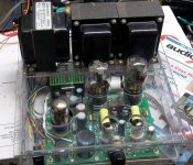
The first Tubelab board was the original TSE. It did not have connectors, just large pads on the board for direct soldering of the wires. During the development of the SSE, connectors were the most requested item since many DIYers tend to tinker with their amps. All Tubelab boards since the SSE have used the terminal blocks, but you don't really need them. When soldering directly, I tend to leave the heavy transformer wires a bit long and leave a loop about 1 inch in diameter between the transformer and the board so that the wires can expand and contract with heat. I have also seen pictures of user's boards where every wire was neatly routed and bundled or laced like an old Tektronix scope. This seems to work too.
The picture shows the very first TSE in a Lexan box with soldered wires.
There is no problem soldering the wires directly to the board, and I often do that in things that see a lot of vibration or movement. I don't recommend using screw terminals in a guitar amp or other application that sits directly on a speaker that gets played loud. There are concerns that should be addressed when soldering directly to the board. Some wires are stiff. The heater wires in question are quite large and can apply stress to the board if the board is forced into its enclosure after all the wires are soldered. Repeated soldering and unsoldering may eventually weaken the pad to board contact resulting in a damaged board.
With my chassis and construction skills, and my propensity for finding the limits of things, I need to take it apart a lot, so I use the terminal blocks. If the design is solid, and the build is considered final, then soldering the wires to the board will theoretically create a more reliable final product, since as you have found, connectors of any kind carry a possible failure mechanism. Just remember that you may need to take it apart someday.
The first Tubelab board was the original TSE. It did not have connectors, just large pads on the board for direct soldering of the wires. During the development of the SSE, connectors were the most requested item since many DIYers tend to tinker with their amps. All Tubelab boards since the SSE have used the terminal blocks, but you don't really need them. When soldering directly, I tend to leave the heavy transformer wires a bit long and leave a loop about 1 inch in diameter between the transformer and the board so that the wires can expand and contract with heat. I have also seen pictures of user's boards where every wire was neatly routed and bundled or laced like an old Tektronix scope. This seems to work too.
The picture shows the very first TSE in a Lexan box with soldered wires.
Attachments
Thank you! This makes good sense.I have heard arguments both for and against tinning the wires before inserting them in a terminal block. I find that a tinning with a minimal amount of solder works best for me, but I tend to take things apart and mess with them a lot. Too much solder will leave a blob somewhere resulting in uneven diameter and only a small contact area which will compress over time. I use just enough solder to keep the strands from moving under vibration.
There is no problem soldering the wires directly to the board, and I often do that in things that see a lot of vibration or movement. I don't recommend using screw terminals in a guitar amp or other application that sits directly on a speaker that gets played loud. There are concerns that should be addressed when soldering directly to the board. Some wires are stiff. The heater wires in question are quite large and can apply stress to the board if the board is forced into its enclosure after all the wires are soldered. Repeated soldering and unsoldering may eventually weaken the pad to board contact resulting in a damaged board.
With my chassis and construction skills, and my propensity for finding the limits of things, I need to take it apart a lot, so I use the terminal blocks. If the design is solid, and the build is considered final, then soldering the wires to the board will theoretically create a more reliable final product, since as you have found, connectors of any kind carry a possible failure mechanism. Just remember that you may need to take it apart someday.
The first Tubelab board was the original TSE. It did not have connectors, just large pads on the board for direct soldering of the wires. During the development of the SSE, connectors were the most requested item since many DIYers tend to tinker with their amps. All Tubelab boards since the SSE have used the terminal blocks, but you don't really need them. When soldering directly, I tend to leave the heavy transformer wires a bit long and leave a loop about 1 inch in diameter between the transformer and the board so that the wires can expand and contract with heat. I have also seen pictures of user's boards where every wire was neatly routed and bundled or laced like an old Tektronix scope. This seems to work too.
The picture shows the very first TSE in a Lexan box with soldered wires.
Another option would be connector blocks like the ones in a car wiring harness, soldered via coloured wires to the board and the different components, then the amplifier can be dismantled and reconnected easily, with minimal risk of wiring issues. I've tried to find a source of those but with no luck so far. Ideally you'd need 2-, 3-, 4- and 5-way, capable of dealing with the voltages. Then there is the matter of crimping or soldering - crimping appears to be the superior option, but needs another tool.
- Home
- More Vendors...
- Tubelab
- Issue with heater wiring in SSE