I have been spending a lot of time dealing with oscillation of my 3EF Diamond OPS. I finally have to cut the Diamond connection of the pre-drivers and connect them to the rail to get rid of the oscillation as shown. Now, it is a 3EF with FOLDED pre-driver stage. I don't know whether you guys encounter any oscillation problem with this, but from my finding, it is a real problem with the diamond design. I like to hear what are your experience.
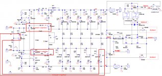
Attached is my schematic. I just use one 2K resistor to pull J2 to +rail and 2K to pull J4 to -rail. then just drive the +ve input with a generator. I have no IPS/VAS, just the OPS with no GNFB, so any oscillation is local.
Attached is the schematic of the OPS. I believe the problem is the pre-driver Q8 and Q10 in the Diamond where the collector is connected to the emitter of Q7 and Q11 resp. The Ccb feed the signal back in phase to the base and create the positive feedback. The frequency is between 4MHz down to 500KHz depending on the length of the coax connecting from the generator to the input. This is not from the normal parasitic, the tell tale is the input coax has a lot of effect to the frequency of the oscillation, so it has to be from the collector of Q8 and Q10 feeding to the base and into the coax. I even try putting a series resistor at the base of Q8 and Q10, it did not help.
Before I connect the collector of the two pre drivers to the rail, I tried putting up to 82ohm resistor in series with the collector to the emitter of Q7 and Q11 to try to current limit, it help, but really depends on the transistor used. I changed from KSC3503/KSA1381 to KSD1691/KSB1151 resp. for reason explain later, it got really bad. I then change to 2SC4793/2SA1930, it is better but still oscillates. So I decided to move the collector to the rail to solve the problem for once and for all.
I managed to play around with collector resistor and RC loading to stop the oscillation with the diamond connection. But when I did the square wave test, I can still see the ringing. I don't think it is safe to keep the 3EF Diamond anymore. Now I really have a solid square wave output with only very little overshoot and die down after one ring.
I think the problem is the Ccb, the larger the capacitance, the worst it is. So I need transistor with low Ccb. BUT, the problem with the 3EF diamond is the bias spreader can only be about 1.1V, One has to be very careful in what transistor to use, AND also the pre-driver has to have very low Vbe in order to give more headroom for the bias spreader. The original KSC3503 and KSA1381 has Vbe of 0.66V, it really killed the headroom. that's the reason I had to change transistor. Problem is all the transistor with low Vbe are high current device and has higher Ccb by default. I settle with 2SC4793/2SA1930 because it has about the lowest Cob and have Vbe=0.58V.
Another problem is when I crank the frequency above 800KHz, the waveform at the output totally collapsed. I have to reduce the R17 to 15ohm to run the drivers at close to 100mA and increase the current of the pre drivers Q8 and Q10 to 28mA in order to increase the frequency to 1.5MHz before collapsing.
The symptom is actually the two driver transistor q7 and Q11 actually turn off at part of the cycle. I speculate that it's the 600pF Cob of the big MJW that actually hold the voltage and I need more tail current in the drivers to prevent the Q7 and Q11 from turning off. The frequency of collapsing depending on the output voltage amplitude of the sine wave. Since the OPS has gain of only unity, I ony get about 8Vpp output as that's the max of the generator. the higher the amplitude, the sooner the output collapses. So I expect the output will collapse at much lower frequency if I drive close to the rails.
Also, part of the problem is the folded pre-drivers that you can only have max current equals to the CCS used. This is another short coming of the Diamond.
Not only the problem of +ve feedback, the tempco of the spreader can be a huge problem. You only have 1.1V to play with. Not a whole lot of room to be creative. I am using two transistor CFP and adjust R37 and the bias pot to balance between the tempco and bias voltage. I am still working on it. I just finish taming the oscillation.
Anyone actually implemented the 3EF Diamond? You experience the low spreader voltage and oscillation problem like me? I would like to compare notes and see whether I missed anything.
All in all, I think it's worthy to spend the time on this folded 3EF as the tempco of the pre driver and the drivers cancels out really well when I screwed them together. It just take time to fix the short comings. I don't see any disadvantage using just the folded 3EF instead of the 3EF Diamond, the main thing is the tempco cancellation of the pre driver and driver stage and the spreader only have to worry about the power transistors. The folder 3EF will do just as good a job as the Diamond.
Attachments
Last edited:
Nobody?
I forgot to mention:
The oscillation gone down to 500KHz when I disconnected the coax that drive the J2. I believe it is because without the coax, the impedance at the input is the parallel of the two 2K resistors that pull up and down to the rail to fix the bias spreader near 0V. The higher the impedance, the lower the frequency Ccb of the Q8 and Q10 be able to feedback to the input and create oscillation.
I tried to cut out two pair of the MJW and observed the frequency of the output collapse goes from 1.3MHz to 1.6MHz. Cutting out two pair reduce the capacitance loading the drivers Q7 and Q11.
I know I should not test at this high frequency, but, I am only testing at 8Vpp, the frequency will go much lower if I can increase the amplitude. Also I believe the OPS needs to be fast, get out of the way of the IPS/VAS. The higher the frequency response, the lower the distortion at audio frequency. Also, I don't want to let the slew rate limit gets in the way. The -3dB of the audio needs to be at least 400KHz as well explained by Ostripper in his CFA designs. You want to have as high a loop gain at 20KHz to have enough loop gain to cancel out the crossover and other distortions.
Also, the more disturbing thing is once is collapsed, it won't recover until I lower the frequency back to 600KHz. This is not good as it has a latching effect. I still don't feel confident that I got to the bottom of the reasoning yet. I tried also with 8ohm load and it does not make any difference to the frequency the output collapse.
Last edited:
Member
Joined 2009
Paid Member
This looks like an advanced circuit with a lot of scope for complex issues. From your comments I am not sure that you have enough experience, even with simpler circuits, from which you can draw up on to solve these problems. Forgive me if I have made the wrong assumption.
With so many things to take into account, including layout, lead dress etc I suggest taking a step back and establishing more experience with simpler designs, proving out the key design elements you are interested in and discovering what really matters to you in terms of the circuit performance. The designs from OS are supported by extensive experience and a thorough understanding of the circuit elements, construction, test and debugging.
With so many things to take into account, including layout, lead dress etc I suggest taking a step back and establishing more experience with simpler designs, proving out the key design elements you are interested in and discovering what really matters to you in terms of the circuit performance. The designs from OS are supported by extensive experience and a thorough understanding of the circuit elements, construction, test and debugging.
Last edited:
Don't worry for me, I solved a lot of stability problems in my career. This is just new, nothing advanced about it. I already resolved the problem before I even posted. I drew my conclusion, I just want to hear from others that worked with 3EF Diamond if they have issue.
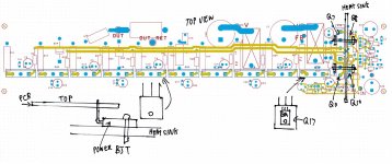
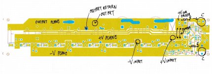
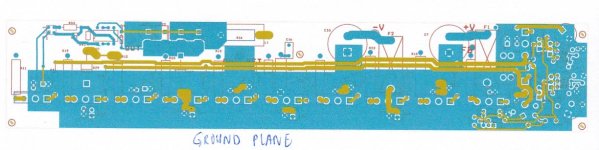
Layout is everything. I layout pcb for circuits for hundreds of MHz and RF for a few GHz. So this is nothing new to me. Attached is the components and traces, the power and output planes layout and the ground plane top layer. You can see, other than the two driver traces and the two input traces that is longer, every signal trace is pretty much point to point. That's why it looks so simple for a big circuit. This layout is good for many MHz.
I have 0.1u and 10uF cap point to point from all the collector of the power transistors to ground plane, I make sure I don't accidentally have holes on any of the planes that create current loop. Layout is NOT a problem. As I said, the frequency is very low, any oscillation caused by ground loop on traces will be at higher frequency, not vary from 4MHz down to 500KHz.
Attachments
Last edited:
Nobody build a 3EF Diamond?
I did experiment with the other board that I don't have the big MJL transistors soldered on yet. I use two RC as load of 0.5ohm in series with the 3300pF( simulate 5 of the MJL each with 2.2ohm base stop). I soldered one on each emitter of the driver transistors to ground to simulate the load of the MJL. I can see the the waveform collapsed at some frequency just like the board with the MJL output transistor. I am looking at 2SC5242 and 2SA1962 which is the TO-3P version of 5200 and 1943 to replace the big MJL as the Cob are almost half of the MJL.
Because of the capacitance load, I even have to increase the current of the pre-driver to 35mA. The pre-drivers and drivers are getting hot particularly if I pump a sine wave of higher frequency. When I run above 300KHz, the current drawn from the supply increases and it went above 2.5A at high frequency. It's a lot of capacitance to drive.
I really like to hear from someone that had successfully designed a 3EF Diamond to compare notes.
Last edited:
I have found that for any BJT output stage, getting to these speeds will mean choosing fast transistors and then biasing the transistors as high as you can get, or using individual push-pull pairs for everything that needs driven. And then you reach the barrier where there is too much phase shift at the frequencies you want to drive the transistors at. You can extend this a bit with phase lead compensations, except that the phase shift at the edge of a BJT's BW can shift by several times during operation which means bursts of oscillation at certain operating points. As far as I know the Diamond is not an exception.
I am designing the oscillation detector as Cordell talked about. Still working on the 4 pole LCLC high pass Butterworth filter, buffer by a high speed opamp like AD8011 400MHz CFA before rectifying and driving the LM555 to light up the LED for 1 second every time a burst of RF appears.
I don't believe I have that problem, but I am going to build that eventually. Seeing is believing. It will take some time as I am busy with my contract work.
Diamond is very different from regular 3EF as explained in the first post. I think I have proven beyond doubt it's not the regular transistor oscillation. The oscillation is not even high frequency. It's only between 500KHz to 4MHz, way below loacal parasitic oscillation. Not all oscillations are the same even it's due to parasitic.
Last edited:
That must be the feedback loop. Have you tried an RC from the predriver bases to ground? Use a large C at first and see if there is an R value that stabilizes it. Then reduce the C as possible.
Phase lead may also help. If your VAS is degenerated, a cap across the degeneration may work.
This sounds like you're running into phase shift problems you tend to get in EF3s. I've used RCs after the predrivers, LC base stopper networks, etc.
Phase lead may also help. If your VAS is degenerated, a cap across the degeneration may work.
This sounds like you're running into phase shift problems you tend to get in EF3s. I've used RCs after the predrivers, LC base stopper networks, etc.
That must be the feedback loop. Have you tried an RC from the predriver bases to ground? Use a large C at first and see if there is an R value that stabilizes it. Then reduce the C as possible.
Phase lead may also help. If your VAS is degenerated, a cap across the degeneration may work.
This sounds like you're running into phase shift problems you tend to get in EF3s. I've used RCs after the predrivers, LC base stopper networks, etc.
I did not try RC to ground at the base of the pre-drivers because that will load the VAS directly.
It is not phase shift. If you follow from the emitter of the pre-drivers, through the drivers. Then back to the collectors of the pre-drivers. It is all IN PHASE. The Ccb of the pre-drivers couple the signal from the collector to the base of the pre drivers to complete the positive feedback.
This is very very different from the regular 3EF. That's what I have been trying to explain. That you have a positive feedback in the Diamond configuration. The only way it will be less likely to oscillate is if the Ccb of the pre-drivers are low and even the high impedance of the VAS will prevent the coupling from the Ccb.
This has nothing to do with the regular parasitic local oscillation. All problem is solved as soon as I cut the collectors of the pre-drivers and connected directly to the respective rails.
I cannot emphasize enough, the oscillation I am talking about has no similarity to the potential oscillation of the regular 3EF. Not at all.
Hi Alan,I have been spending a lot of time dealing with oscillation of my 3EF Diamond OPS.
[...]
it is a real problem with the diamond design. I like to hear what are your experience.
[...]
Some of my simulations of a diamond driver also showed up instability. I cured it (simulation wise) with 100 Ohms in series with the collectors of the pre-drivers. Did you try this as well?
Cheers, E.
[...]
Another problem is when I crank the frequency above 800KHz, the waveform at the output totally collapsed. I have to reduce the R17 to 15ohm to run the drivers at close to 100mA and increase the current of the pre drivers Q8 and Q10 to 28mA in order to increase the frequency to 1.5MHz before collapsing.
[...]
Hi Alan,
Optimizing an OPS way beyond audible frequencies is overkill. Apart from increased dissipation, it may be even counterproductive, as the performance at AF might suffer at these high currents (e.g. lower beta).
Cheers, E.
Forgive me, I'm sure I seem like a senile old man (no offense to old men who are senile). I don't have much time to think a lot about my replies.
It would help to see the frontend you're using. That certainly doesn't help me NOT look like a fool.
This is still sounding very familiar. High impedance VAS with highly buffered output stage is generally an ominous combination. Is there a miller capacitor to the VAS node or not?
With the predrivers connected like a Baxandall, they may be in quasi-saturation. In this region Ft can drop terribly. This increases loading and phase shift through the VAS. Look at the datasheet and see what happens to the Ic curves at 0Vcb. They should be flat at the intended Vce. The vast majority of high-voltage transistors don't handle this well. Furthermore since few simulation models include quasi-saturation, your prototype may work well in simulation but badly in real life.
It would help to see the frontend you're using. That certainly doesn't help me NOT look like a fool.
The only way it will be less likely to oscillate is if the Ccb of the pre-drivers are low and even the high impedance of the VAS will prevent the coupling from the Ccb.
This is still sounding very familiar. High impedance VAS with highly buffered output stage is generally an ominous combination. Is there a miller capacitor to the VAS node or not?
With the predrivers connected like a Baxandall, they may be in quasi-saturation. In this region Ft can drop terribly. This increases loading and phase shift through the VAS. Look at the datasheet and see what happens to the Ic curves at 0Vcb. They should be flat at the intended Vce. The vast majority of high-voltage transistors don't handle this well. Furthermore since few simulation models include quasi-saturation, your prototype may work well in simulation but badly in real life.
Hi Alan,
Some of my simulations of a diamond driver also showed up instability. I cured it (simulation wise) with 100 Ohms in series with the collectors of the pre-drivers. Did you try this as well?
Cheers, E.
Hi Edmond
Yes, that was the first thing I tried. It helped a little, but did not stop the oscillation. I first managed to stop the oscillation on the second board that dose not have the power transistors. It did stop the oscillation. But when I did the modification on the board that has all the transistors, it did not work. The extra capacitance of the big transistors pushed it over the edge.
Because it's so sensitive to the input cable, I even tried a base stop for the predrivers and seems to make it even worst.
I tried 0.1u across the spreader, across the base collector of the NPN spreader transistor, I even shorted out the spreader all together, it did not do anything.
I tried different pre driver transistors, the higher current ( bigger die with higher Ccb) transistor is worst. Even 2SC4793 with only 26pF still oscillated in much lower amplitude. Only the KSC3503 pair with 2.6pF did not oscillate. But still I can feel it's on the edge.
Hi Alan,
Optimizing an OPS way beyond audible frequencies is overkill. Apart from increased dissipation, it may be even counterproductive, as the performance at AF might suffer at these high currents (e.g. lower beta).
Cheers, E.
Yes, I understand this. Just itchy fingers!!!

But seriously, I do that as a way to test for oscillation. Just observing the overshoot and ringing using a square wave is not a reliable way to rule out oscillation. I found sweeping the frequency way beyond the operating frequency and look at the wave shape and amplitude as you roll up the frequency can tell more on the stability. You might see the wave shape change at some frequencies or another higher frequency modulate on the original sine wave or some funny twitches. These all indicate potential oscillation problem.
Bottom line, I don't depend on just looking at the scope to tell me whether there is oscillation, I try to trigger it to oscillate.
Also, I turn the power on and off and look, changing the rail voltage as it is common for oscillation to occur when changing the operating parameters.
Thanks
Last edited:
Forgive me, I'm sure I seem like a senile old man (no offense to old men who are senile). I don't have much time to think a lot about my replies.
It would help to see the frontend you're using. That certainly doesn't help me NOT look like a fool.
This is still sounding very familiar. High impedance VAS with highly buffered output stage is generally an ominous combination. Is there a miller capacitor to the VAS node or not?
With the predrivers connected like a Baxandall, they may be in quasi-saturation. In this region Ft can drop terribly. This increases loading and phase shift through the VAS. Look at the datasheet and see what happens to the Ic curves at 0Vcb. They should be flat at the intended Vce. The vast majority of high-voltage transistors don't handle this well. Furthermore since few simulation models include quasi-saturation, your prototype may work well in simulation but badly in real life.
Hi keantoken
I welcome any question.
I don't have a front end, I just use coax to drive into the OPS board. It does not have gain and no GNFB. I specifically do this to test for oscillation before I even put the IPS/VAS together.
I figure the output of VAS is high impedance, I even removed the coax, the oscillation frequency gone down to 500KHz. My theory is the higher the impedance, the more the signal feed back through the Ccb of the predrivers and the lower the frequency you reach the positive feedback gain of +1. That's the tell tale that the problem is signal through the Ccb back to the input. Changing the length of the coax change the frequency also because of the changing of the capacitance of the coax to ground.
The predrivers is not close to saturation, they have at least 1.5V between the collector and the base, the base collector diode of the transistor is definitely reverse biased. But yes, it is lower than the voltage the data sheet used to test Ccb. So it's going to be higher than the datasheet.
Thanks
Alan
I have a question about your input. On your original schematic, you have a + and - input and ground. My problem is that the + and - should be the same signal, separated by spreader voltage. (usually with a cap between them.) I would think it would be better to have a coupling cap to both inputs with one signal for testing (and a cap between them).
I have a question about your input. On your original schematic, you have a + and - input and ground. My problem is that the + and - should be the same signal, separated by spreader voltage. (usually with a cap between them.) I would think it would be better to have a coupling cap to both inputs with one signal for testing (and a cap between them).
Yes, I did put a big cap across the spreader with 0.1uF. I even shorted the spreader together. I am not testing distortion at this point, I only try to get it to oscillate and fix it first.
thanks
Yes, I did put a big cap across the spreader with 0.1uF. I even shorted the spreader together. I am not testing distortion at this point, I only try to get it to oscillate and fix it first.
Did it ever occur to you that perhaps it's the high gain CFP spreader that it is oscillating?
The bias spreader is a shunt constant voltage power supply; as such, it has it's own local feedback loop, with it's frequency compensation provided exactly by the output cap. 0.1uF as about as bad as you can add, it is likely the worse case for transforming the shunt regulator into an oscillator. Lots of shunt and series regulators (IC and discrete) are very happy with an 100uF electrolytic cap (ESR and ESL included) at the output, but behave very badly when adding a 10nF-1uF (low ESL and ESR), they may oscillate as hell. Take a LM337 negative voltage regulator IC and try the same 100uF || 0.1uF at the output... or even a low ESR/ESL tantalum cap and note the results. Or a TL431 shunt regulator with the same. It is also funny that the worst capacitive load for a power amplifier (yet another example of "variable series voltage regulator") is NOT the standard foil 1uF cap used to measure the overshoot, but a 50-100nF (again low ESR/ESL) ceramic cap. Without the Zobel and the output inductor, very few amplifiers will survive such a capacitive load.
You were several time advised to give up this ultra high gain CFP spreader, until you understand it's operation and quirks. Once again, try first a simple spreader from your favorite book.
It is not the spreader. I had bypass cap across the base collector of the NPN spreader, across the whole spreader. I shorted out R37 to turn off the PNP, it's the same. I even shorted out the whole spreader and made no difference in the oscillation.
Those were about the first thing I did right from the beginning to rule out the spreader. It is not the spreader, has never been the spreader.
Those were about the first thing I did right from the beginning to rule out the spreader. It is not the spreader, has never been the spreader.
It is not the spreader. I had bypass cap across the base collector of the NPN spreader, across the whole spreader. I shorted out R37 to turn off the PNP, it's the same. I even shorted out the whole spreader and made no difference in the oscillation.
Those were about the first thing I did right from the beginning to rule out the spreader. It is not the spreader, has never been the spreader.
And how did you biased the output if you shorted the spreader? Or it's oscillating even at zero bias?
Anyway, you are likely doing something wrong, very wrong there. But you got the expected result when starting a project that is way beyond your understanding and experience.
If you care to use the Search option on this site, you will find multiple designs with diamond driver/buffer (both bipolar and mosfet). I have never heard of such a dramatic stability problem in this topology, normally a light band aid (as the collector resistors) is all what's needed. You can try to reproduce one or more of those designs, as a starter. I certainly doubt you will get more help than you already got here.
- Status
- Not open for further replies.
- Home
- Amplifiers
- Solid State
- Issue with 3EF Diamond