Poop! my theory's have proven highly unsuccessful! But you knew that already lol
From isolators secondary to light bulb. Dialed up to 40v and dang nabbit, I measure 23v from the hot on the bulb to the earth ground. I know to expect ghost voltage, but measured 1.2mA on a dead short from hot to earth..
All of this while there is absolutely no continuity between the secondary's neutral and chassis ground, even less continuity between the secondary's neutral and the auto transformers earth ground.
I even tried disconnecting the chassis ground on the isolation rig, and holy batman... STILL have potential from the secondary and the chassis... How the heck does an un-earth grounded chassis have any thing to do with any of this ?
The manufacturer had 2 400 volt capacitors from the hot leg to neutral.. Im figuring to suppress noise... I couldn't read their values as they were installed to be tamper resistant. Basically you have to take a chance getting them out to read them. Well, one came out ok, the other ones leg broke off right inside the case.. I will be pitting up a "what is this part?" soon.. Anyway... Im already elbow deep, figured keep going... Removed the caps and well, Im here complaining, so its safe to guess Im in over my freaking head... (And I want to build a tube amp????)
I have to start somewhere....
Next I will see if there is any connection from the light bulb to my main house ground
Do you still get the 23V with the shield grounded? You are looking at the internal capacitance between the shield and the secondary, or primary to secondary. It can be pretty high. Typically much higher in toroid transformers. The caps on the output are for noise suppression. They would need to be X Caps designed to fail open since an internal short would cause a fire. My guess is probably .47 uF/400V. That would have a shunt current of 20 mA @ 60 Hz. However i have seen applications with 20 uF across the line.
If you are careful building a tube amp can be safe. But high voltages are not something to be casual about.
If you are careful building a tube amp can be safe. But high voltages are not something to be casual about.
Update... And not one that I'm happy about..
Dialed up to the auto transformer to 120v. had 120v on the secondary of the the toroidal's output as well.
Simulating a dead short with my volt meter from the hot leg all the way to my mains house ground get 68.3 volts... Beginning to think that there is no such thing as isolation!
I put that 68.3 through (2) 100ohm 5w resistors which measured at 199ohms and measured .910 AMPs..
I have just about torn this isolation unit completely apart, and don't understand...
Is it the toroidal's causing this? should I try to retrofit the unit with a different type of 1-1 transformer ?
> 120v .....dead short with my volt meter from the hot leg all the way to my mains house ground get 68.3 volts... ...I put that 68.3 through (2) 100ohm 5w resistors which measured at 199ohms and measured .910 AMPs..
Does not add up.
0.91A in 199r is 181 Volts... more than you have in the house. 68.3V in 199r ought to be 0.34 Amps.
Does not add up.
0.91A in 199r is 181 Volts... more than you have in the house. 68.3V in 199r ought to be 0.34 Amps.
What do you get from the neutral leg back to input side ground? Also as a sanity check measure the voltage across the resistors to confirm the current. You should also check DCR from a primary to any secondary. It should be open.
1audio,
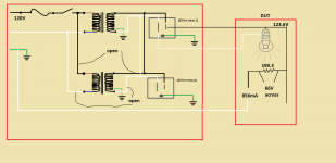
Attached is what and how I measured. I must be missing some fundamental physics lesson..
Added to the circuit the outputs of the secondary's are in parallel behind the outlets. thought that might be important to know...
The voltage drop across the resistor in the DUT and its resistance dont add up to the amperage measured. Ohms law isn't wrong, must be me.
I did take these measurements across the 199 resistor WITH the light bulb in place, could that be messing with me ?
Then, what does the hot leg of the neutral have anything to do with the mains earth ?
Attachments
Life lesson learned....
Lesson learned! When measuring amperage DONT FORGET TO MOVE PROBE ON METER TO CORRECT LOCATION!
Had .2 volts from hot leg of dut (light bulb @123v) to house earth/neutral, and 0 amps to house earth/neutral!!!
Lesson will never be forgotten...
Sometimes the answer is right in front of your face..
Now to re-assemble.
Last edited:
That makes lots more sense (and now you know the quirk of your meter. I have several and the one I used most recently reads zero if the probe isn't moved on amps.)
The GFCI recommendation comes from the NEC for use with isolation transformers and really is a worst case safety issue, unless the secondary center tap is tied to ground.
Remember for high voltages (over 40V) keep one hand in your pocket.
The GFCI recommendation comes from the NEC for use with isolation transformers and really is a worst case safety issue, unless the secondary center tap is tied to ground.
Remember for high voltages (over 40V) keep one hand in your pocket.
- Home
- Design & Build
- Equipment & Tools
- Isolation transformer "adjustment"