Disclaimer first. I am aware that Im a highly untrained non professional. Any advice given to me may kill me and I will be at fault regardless of the quality of information or misinformation given!!!
So, that off my chest.
The audiophile journey is in full swing...
Oscilloscope- Check.
Auto transformer - Check.
Function generator - (On its way!)
Isolation transformer - Kinda-check...
I wont mention the type of isolation transformer I bought (PM me) but upon opening the case I see two Toroidal transformers stacked on top of each other.
The primary wingdings are colored black and blue.
The secondary are white, black and green.
The chassis ground lug originally had quite a few wires; main power cable ground, isolated outlet's ground, isolated outlets neutrals, and secondary transformer green...
To float my o-scope I disconnected the isolated outlets earth and neutral's from the chassis lug.
At first I left the following connections on the chassis lug, power ground and secondary winding's green wire. I dialed in 20V to the auto transformer, turned on the isolation transformer and low and behold measured 20V from isolated hot to neutral. I than measured hot to chassis and poop.. I had 20V....
So I disconnected the secondary winding green from chassis and it looks like I can float my scope..
To be sure, should the isolated ground's be 100% disconnected from everything ?
Does it sound like I missed anything ?
EDIT...
I said float my scope, i meant float the DUT...
My scope will be plugged directly into house mains on a fully functioning outlet
Last edited:
Floating a scope is a dangerous, bad idea. Get a differential voltage probe instead. An example:
https://www.newark.com/pico-technol...SA-GEN-Shopping-NewStructure-Test-Measurement
https://www.newark.com/pico-technol...SA-GEN-Shopping-NewStructure-Test-Measurement
Last edited:
is it better to float the O'scope or the device under test?
is it just me, i understand that isolation is important and the proper reference is necessary for correct measurements but i think that not utilizing the differential capabilities of their scope is an oversight and can solve some headaches.
is it just me, i understand that isolation is important and the proper reference is necessary for correct measurements but i think that not utilizing the differential capabilities of their scope is an oversight and can solve some headaches.
My O-scope will be connected to the house electric the old fashioned way..
Equipment I may be working on will be plugged into the isolation transformer which will be in turn plugged into the auto transformer.
I see now I will be floating my DUT!
And I know I can still get hurt on the isolated side if I get caught between hot and neutral.. and caps will bite just at bad..
The terroidials secondary ground connections that are getting me..
Scopes have limited differential measurement capabilities, and the probes are not matched,
which is necessary for any precision.
which is necessary for any precision.
I hoped this would be a discussion on the isolation transformer mod.
Hence the subject Isolation transformer "adjustment"
I have a set of differential probes as well. 😀
And a smoking hot piece of plastic in my wallet lol..
Hence the subject Isolation transformer "adjustment"
I have a set of differential probes as well. 😀
And a smoking hot piece of plastic in my wallet lol..
Last edited:
It would help if you could draw a schematic of what you think the transformer circuit is. The transformer would not need a connection to ground if isolated. I would very strongly suggest adding a GFCI on the output side for protection.
Isolation transformers are helpful for hot chassis repairs, but those were never part of high end audio. It won't protect you in any way from problems in the chassis and I would never float a scope the way you describe. However I would use something like this https://www.amazon.com/Oscilloscope...ld=1&keywords=DSO1511E+&qid=1607668736&sr=8-1 since its battery powered and can float safely, maybe use an insulated tool to push the buttons. Still better to get HV rated probes and use the scopes differential input. Two relatively identical probes can be adjusted unless you need really high CMRR.
Isolation transformers are helpful for hot chassis repairs, but those were never part of high end audio. It won't protect you in any way from problems in the chassis and I would never float a scope the way you describe. However I would use something like this https://www.amazon.com/Oscilloscope...ld=1&keywords=DSO1511E+&qid=1607668736&sr=8-1 since its battery powered and can float safely, maybe use an insulated tool to push the buttons. Still better to get HV rated probes and use the scopes differential input. Two relatively identical probes can be adjusted unless you need really high CMRR.
A photo as well as a schematic will make your description much more digestible.
What are you trying to measure/scope that requires "isolation"?
What are you trying to measure/scope that requires "isolation"?
Ok, again... I am a buffoon. I said float the scope, but SHOULD have said float the DUT.

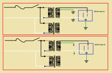
The attached image, shows 4 outlets in my rig. 2 toroidal's in parallel.
The top image shows the stock setup.
The bottom shows the modifications I made. I had to disconnect from the chassis lug, and heat shrink over every ground marked X.
I think I figured out that the secondary's ground (green) was tied into the neutral somewhere deep in the winding. None of the schematics I have seen showed this....
For those who wonder what this is all about, its almost gets you to
"bird on a wire" around high voltage. If you keep one hand in a pocket, you may fry a finger or hand (if you close a circuit with your skin) but you shouldn't get any unplanned electric through the heart action...
Isolation Transformers - YouTube
How to Make an Electronics Workbench Variac (variable autotransformer) - YouTube
Big Dim Bulb Tester with Variac and Isolation Transformer - YouTube
Attachments
This is a start. I suspect the green wire is a shield. If it has no dc resistance to ant winding then it's a shield. However it may be a center tap on the secondary but then connecting to the White wire would short the secondary which would be bad. Floating the secondary is OK but won't offer any new safety protection unless the chassis is "hot". If the green wire is a shield then open its voltage will be determined by the interwinding capacitance. It should return to a ground to block some of the emi on the power line.
What I think, the green is connected to the neutral. A single wire as a shield in a sea of copper wingdings, couldn't do much... And the factory wiring clearly had it tied to the chassis.... If its connected towards the end of the line, say just before the white leaves the winding, it would be the same as the neutral and grounds connected in your fuse panel. The only way for me to disconnect the ground from the the actual plug to the isolated power supply and the neutral of the isolated receptacle was to disconnect the green from the secondary winding and chassis..
It is the only part of this I wasn't expecting.. As it stands now, I left (as shown) the earth ground to chassis (which also has a path through the auto transformer and from there to my homes earth ground.) But, now the secondary winding is fully isolated, and any induced current from it wouldn't recognize a true earth ground as a short cut or path back home...
It is the only part of this I wasn't expecting.. As it stands now, I left (as shown) the earth ground to chassis (which also has a path through the auto transformer and from there to my homes earth ground.) But, now the secondary winding is fully isolated, and any induced current from it wouldn't recognize a true earth ground as a short cut or path back home...
With power removed, a dc continuity check with a multi-meter should establish if there's any connection of the green wire to any other winding Assuming there's no internal joining connection of the green lead, i can't imagine anything other than a shield. This shield is often a foil layer with a lead brought out.
If the continuity check confirms a tapped connection, a couple of ac voltage checks re the green lead should establish where the tap's relative position is located.
If the continuity check confirms a tapped connection, a couple of ac voltage checks re the green lead should establish where the tap's relative position is located.
The attached image, shows 4 outlets in my rig. 2 toroidal's in parallel.
The top image shows the stock setup.
Isolation Transformers - YouTube
How to Make an Electronics Workbench Variac (variable autotransformer) - YouTube
Big Dim Bulb Tester with Variac and Isolation Transformer - YouTube
The isolation transformer pulled up a neat but irrelevant video about a bucket T hot rod. The others are more relevant.
Does the green wire come only from 1 transformer? Shielded toroids are less common, substantially more work to make.
I cannot emphasize enough how important a GFCI would be in this application. Even better an arc fault GFCI https://www.amazon.com/Leviton-AGTR...MTN4?source=ps-sl-shoppingads-lpcontext&psc=1
The isolation transformer pulled up a neat but irrelevant video about a bucket T hot rod.....
Actually: right video, but a TIME pointer to the extra-content at the end.
Try this link (without the t=1709s parameter):
Isolation Transformers - YouTube
I cannot emphasize enough how important a GFCI would be in this application.
The green comes from both secondary's on the toroidals
I fail to understand the GFCI protection, may be I misunderstand its function.
The ground after an isolated circuit is completely removed from the circuit, not in physical sense but in physics. In a normal house hold circuit, the neutral IS tied to the ground. The electrons from the power plant simply want to have a path back. In a normal circuit, the earth presents it self as a path that is supposed to provide less resistance than your body (say a restive short against chassis).
The GFCI acts when the current through the hot leg does not match the current in the neutral. The only way this can happen is when neutral is also tied to earth. Now the electrons can flow through the ground lug, and cause an imbalance in the hot and neutral, tripping the circuit open.
All can think of that would allow the isolator in question to function like this would be to add a pig tail on the neutral (white) on the secondary and have the pig tail tied to the ground lug on a GFCI outlet?
Interesting idea...
Right now, Im going to reread previous posts, open the isolator back up, take some measurements. I'm curious if the green is a shield or..
I dont want to keep making changes, or modifications unless Im 100% confident...
All who said Green was a shield were 100% on the money!
There is no continuity between that and any other connection inside the box...
After reconnecting it to the chassis, neutral on the secondary and the chassis are not connected at all.
To change to GFCI or remove the earth to chassis connection will require new receptacles... the lower bracket that holds the receptacle to the chassis is using one screw that also doubles as the ground wire lug..
As an FYI... The toroidal's have a label, YOUWON DV-130-1
Nothing I can find except an ebay add...
The GFCI acts when the current through the hot leg does not match the current in the neutral. The only way this can happen is when neutral is also tied to earth. Now the electrons can flow through the ground lug, and cause an imbalance in the hot and neutral, tripping the circuit open.
* * * * * * * * *
Not the only path. Current could make it's way back thru leakage to other circuits.
* * * * * * * * *
Not the only path. Current could make it's way back thru leakage to other circuits.
A GFCI triggers at pretty low leakage current, 5 mA which could be leakage or who knows what. Still low enough that you won't get seriously injured. You use it because you could have a problem with your DUT OR your power source has some internal breakdown. The Arc fault feature would help protect and spot bad or shorting connections, not unusual on vintage equipment.
If you have the tool you can measure the capacitance between the shields and the secondary. Them measure the voltage between the secondary taps and the shield with a hi-Z meter to determine which end of the secondary is closest to the shield. This would minimize the leakage current if that end is used the neutral, usually.
If you have the tool you can measure the capacitance between the shields and the secondary. Them measure the voltage between the secondary taps and the shield with a hi-Z meter to determine which end of the secondary is closest to the shield. This would minimize the leakage current if that end is used the neutral, usually.
Not the only path. Current could make it's way back thru leakage to other circuits.
Speedskater, and 1audio
If there are only 2 wires from the secondary on the isolation transformer (hot and natural) what path would you be talking about ?
Even if the Chassis is grounded, that ground has no reference to the secondary (right now anyway..)
Am I still missing something ?
There are still leakage paths plus the hazard of an unintended breakdown in the transformer or internal wiring in the box. Its more important if you have a grounded center tap, another popular isolation configuration. Probably it would not be necessary, like fuses, until it is.
Let me touch on another misunderstood aspect in power wiring. That ground connection is a safety feature. Its function is to shunt any short paths to ground AND create a fault current enough to blow fuse/open circuit breaker and protect user/equipment. Noise considerations are secondary. And I much prefer the 5 mA trip of a GFCI to the 15A+ of a (US) residential circuit breaker when something goes wrong.
Let me touch on another misunderstood aspect in power wiring. That ground connection is a safety feature. Its function is to shunt any short paths to ground AND create a fault current enough to blow fuse/open circuit breaker and protect user/equipment. Noise considerations are secondary. And I much prefer the 5 mA trip of a GFCI to the 15A+ of a (US) residential circuit breaker when something goes wrong.
- Home
- Design & Build
- Equipment & Tools
- Isolation transformer "adjustment"