Hi,
I am developing my construction corner, the lab bench I'm using for building and measuring stuff at. I intend to have a bunch of voltage sources like PSUs and lab transformers on the left side and my measuring equipment like oscilloscopes and signal generators on the right side.
In the past I have experienced problems when doing small signal measurements. I have experienced all sorts of problems with external disturbances like distance to lamps affecting the probes and dirty mains from cheapo wallwarts plugged in here and there.
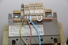
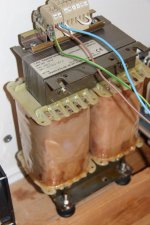
So I thought I would make it semi-pro for once. To start with I will have an isolation transformer feeding all the sensitive equipment. I have a 2000 VA with an interwinding isolation copper layer and also an outer "belly-band".
Each isolation layer has its own connection on the transformer so my first question is, how do you folks say I should connect them? My latest recommendation is the interwinding layer to mains PE and the outer "belly-band leaved floating. Is that the optimum/right way?
Next question is that I would like to have not only the N and Feed AC line cleansed but also the mains PE. They sit together somewhere down the line thus dirt on N affects the PE just the same. So I prefer not to have that on "the measuring table". My transformer has a dual 115+115 VAC secondary so I have learned that I could use the center tap as a Virtual Protection Earth. As far as I know that is ok and that is how it works in for example american households. Is that ok?
If so. When I test run the transformer unloaded it produces an inducted 40 VAC between the mains PE and the secondary CT. When I measure current this is some 40 uA so theres hardly any current and I can short it with my fingers without feeling it. When shorting PE and CT the windings give nearly exactly the same between secondary and PE, the same as between secondary lines and its and CT.
So for optimum results and workability on my test bench, what would you electrical engineers do? Leave the secondarys floating or reference it in some way? I tested with a 5H, 50 mA 250 ohm DCR Hammond inductor and it braught the voltage down to some 2 V between mains PE and secondary CT.
Opinions professionals?
I am developing my construction corner, the lab bench I'm using for building and measuring stuff at. I intend to have a bunch of voltage sources like PSUs and lab transformers on the left side and my measuring equipment like oscilloscopes and signal generators on the right side.
In the past I have experienced problems when doing small signal measurements. I have experienced all sorts of problems with external disturbances like distance to lamps affecting the probes and dirty mains from cheapo wallwarts plugged in here and there.
So I thought I would make it semi-pro for once. To start with I will have an isolation transformer feeding all the sensitive equipment. I have a 2000 VA with an interwinding isolation copper layer and also an outer "belly-band".
Each isolation layer has its own connection on the transformer so my first question is, how do you folks say I should connect them? My latest recommendation is the interwinding layer to mains PE and the outer "belly-band leaved floating. Is that the optimum/right way?
Next question is that I would like to have not only the N and Feed AC line cleansed but also the mains PE. They sit together somewhere down the line thus dirt on N affects the PE just the same. So I prefer not to have that on "the measuring table". My transformer has a dual 115+115 VAC secondary so I have learned that I could use the center tap as a Virtual Protection Earth. As far as I know that is ok and that is how it works in for example american households. Is that ok?
If so. When I test run the transformer unloaded it produces an inducted 40 VAC between the mains PE and the secondary CT. When I measure current this is some 40 uA so theres hardly any current and I can short it with my fingers without feeling it. When shorting PE and CT the windings give nearly exactly the same between secondary and PE, the same as between secondary lines and its and CT.
So for optimum results and workability on my test bench, what would you electrical engineers do? Leave the secondarys floating or reference it in some way? I tested with a 5H, 50 mA 250 ohm DCR Hammond inductor and it braught the voltage down to some 2 V between mains PE and secondary CT.
Opinions professionals?
Attachments
The secondaries MUST not be connected to the primaries or Earth in any way! They must be totally isolated.
Are you sure about the mechanisms which cause interference, and how the suggested fix should address them? From your post I can't judge the circumstances in sufficient detail, but more often than not "isolating ground" or "cleaning mains power" causes at best no further problems...
Working solutions tend to have more to do with reducing loop area, both at the offending and receiving end. At audio frequencies, using differential probing is also very effective.
I've found "Grounding and Shielding: Circuits and Interference" by Ralph Morrison to be an excellent guide to the actual physics of interference. It gave me at least a basic understanding of the nature of EM fields, and the importance of conductor geometry.
Samuel
The secondaries MUST not be connected to the primaries or Earth in any way! They must be totally isolated.
agreed, otherwise why use isolation transformer at all...
Ok thank you. I will work on the plan to leave secondaries floating and use CT as a virtual PE then. AJT, as a transformer constructor, do you have opinions of the transformer shield layers, where to connect them?
make sure that that CT is not electricaly conected to any primary circuit....
the mechanical frame of your isolation traffo should be earthed....
pay no significance to any voltage you measure between your CT and PE...
the mechanical frame of your isolation traffo should be earthed....
pay no significance to any voltage you measure between your CT and PE...
Hello Stajo,
As already said, any secondary wire must not be connected to PE, but you can use the PE in both side of transformer (PE in = PE out).
Like this picture below :
With this configuration, you avoid that output voltage float much from ground
and allow HF return path to all parts between isolated output lines and PE (like Y capacitors of main filter). That is clearly better for EMC.
FRex
Mains power is dangerous for three reasons.
It is highish voltage
It is high current.
It needs ONLY one hand on a Live part to take current back to Earth.
It's this last that makes it VERY DANGEROUS !
By using an isolation transformer you change that last problem.
With an isolation transformer that has the output NOT connected to Earth, one needs TWO hands connected across the highish voltage for current to flow.
That is the fundamental difference between Mains power and isolated power.
Frex. Since N and PE is connected somewhere down in the electrical system, are you sure that is the best way to let the mains PE go up on the bench in full? I assumed that a CT as a virtual PE would also function as a HF return path. Or am I wrong?
Well said Andrew!
Stafan
Running the risk of getting more confused, here is a thread that you might like to go through 🙂
http://www.diyaudio.com/forums/everything-else/142631-question-about-how-wire-isolation-transformer.html#post1807414
George
Stafan
Running the risk of getting more confused, here is a thread that you might like to go through 🙂
http://www.diyaudio.com/forums/everything-else/142631-question-about-how-wire-isolation-transformer.html#post1807414
George
interference is referenced to EARTH (common mode), or across a PAIR of wires (differential mode). Q to the experts, have I got the modes correct?
Interference coming in via the mains cables needs to be returned to EARTH.
That is done via capacitive coupling for the higher frequencies and by the lower impedance of capacitive coupling and PE, for the lower frequencies.
If you want to attenuate higher frequency noise, it must be returned to a transformer enclosing Faraday cage that is capacitively coupled to EARTH.
Without an enclosing conductive box the interference will be radiated from the exposed transformer to any aerial loops on your test bench.
You must also minimise the loops of the connecting cables to and from the transformer.
For even better interference performance the connecting cables can be screened and the screens are connected to that box via low impedance connections.
Thanks for that link.Well said Andrew!
Stafan
Running the risk of getting more confused, here is a thread that you might like to go through 🙂
http://www.diyaudio.com/forums/everything-else/142631-question-about-how-wire-isolation-transformer.html#post1807414
George
I still have my isolating transformer to wire up.
That hopefully has all the answers.
Hello Stajo,
As already said, any secondary wire must not be connected to PE, but you can use the PE in both side of transformer (PE in = PE out).
Like this picture below :
With this configuration, you avoid that output voltage float much from ground
and allow HF return path to all parts between isolated output lines and PE (like Y capacitors of main filter). That is clearly better for EMC.
FRex
I too am afraid that bring any PE, either real or virtual, onto the test bench brings back the same problem as when using Mains power.Frex. Since N and PE is connected somewhere down in the electrical system, are you sure that is the best way to let the mains PE go up on the bench in full? I assumed that a CT as a virtual PE would also function as a HF return path. Or am I wrong?
If one does not have any PE on the bench and all equipment is powered from the isolating transformer, then you will need TWO hands to get any electrical shock.
If there is a virtual PE to the bench, is there a risk of bringing back the ONE hand shock hazard?
Well said Andrew!
Stafan
Running the risk of getting more confused, here is a thread that you might like to go through 🙂
http://www.diyaudio.com/forums/everything-else/142631-question-about-how-wire-isolation-transformer.html#post1807414
George
Phew🙂 Funny that there are so many completely opposite different "do's and don'ts" from initiated people.🙂
Well said Andrew!
Stafan
Running the risk of getting more confused, here is a thread that you might like to go through 🙂
http://www.diyaudio.com/forums/everything-else/142631-question-about-how-wire-isolation-transformer.html#post1807414
George
The expression still confused but on a higher level is suitable after reading those pages. Im putting on the tele...😀
Hello,
Using an isolation transformer with same PE wire at input and output allow of course to keep it safe.
You will need to touch two wire to be electrified.
Touching only one wire (between your hand and your feets for example) will have no effect because
your two secondary wires are NOT referenced to PE wire (by only parasitics capacitance).
On this configuration (the picture i posted previously), the PE is intended as path for EMI,
but NOT for personal protection (when combined with differential breaker).
I use that every days on my lab.
Frex
Ok. So now I will ponder a while weather to use CT as ground for the instruments or if I shall pull the yellow/green mains PE to the cabinets. A question here: do instruments like scopes, function gen's, PSUs etc usually have internal PE references on secondarys as usually done in amp PSUs?
Last edited:
All ClassI equipment will have PE connected to the main conductive metalwork. This could be a chassis baseplate, or a big heatsink, or an enclosing Faraday Cage.
The scope is a bit different. It too has the normal PE to enclosing Chassis.
The scope also has the ground lead of the probes connected to that same Chassis. i.e. PE is brought right to the probe ground lead.
It is this PE connection that causes some of the measurement problems we see when using a scope.
We MUST maintain the scope PE connection. The scope is not fed from the isolated supply.
If the DUT is isolated and in effect floating, then when the probe ground is connected, the DUT has that TEST POINT connected to PE and all other parts of the DUT are now voltage referenced to that test point.
Q.
To all the experts out there.
Is there anything wrong with the statements in THIS post?
I will get the Moderators to change/eliminate any errors as necessary
Last edited:
I am not an expert on EMI and avoiding it................................On this configuration (the picture i posted previously), the PE is intended as path for EMI, ...............
Most of what I have is either from this Forum, or from H.Ott.
According to H.Ott the effective route for EMI is capacitive coupling to "EARTH"
This "EARTH" being the big 13Mm ball that we all stand on.
I consider the PE connection as not being effective for EMI attenuation at high frequency.
The PE connection is very long. It has much impedance due to the length.
PE is effective for 50/60Hz and the low harmonics of this. It is the recognised and mandatory connection for mains frequency grounding and for mains frequency interference back to "EARTH".
Last edited:
Attachments
- Status
- Not open for further replies.
- Home
- Design & Build
- Equipment & Tools
- Isolation tranformer to lab bench