Hello,
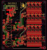
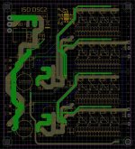
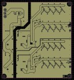
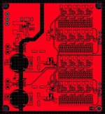
This is fully isolated DSC2 DAC project, I'm finished this dac and here is project files for their build. Curently I'm not tested this but my hope somebody from you do it. Note that main buck regulator accept maximum 100V and minimum 5V at the DC imput, and I have set fixed 4.4Vout from the buck. You no need clean DC on DC input since push pull and LT3042 will make clean supply DC voltage for DSC2. Main care must be done to iso push pull reglators because it not accept more than 5.5V!!! You need to wire ferite to 1.2mH on primary and on secondary you need to have 7V, so please do the things carefully right before you put the rest of components on board! Take a look to schematic!
PCB dimension: 90 x 81.5 mm
Ferite is: FEPTN10/6-3E25
dimension: 10,6x5,2x4,4 mm
AL 2250nH
Primary: 1.2mH + 1.2mH, with center tap! Secondary - do it yourself for 7 Vout.
DSC diff current: my choice was 8mA diff, if you need less calculate your resistor values for dsc! My choice was 10k resistors since my i/v frontend accept this value. This is also I think good enought for an transformer based i/v, and I used those 10k values in original dsc2.5.2 with this audio transformer -> https://it.aliexpress.com/item/32810421236.html
Resitor value calculation formula for IdiffMax=+-8mA :
5V / ((0.008A / 32) + (0.008A / 32)) = Rvalue
C_NP and R_NP components if need! Its connected to one of the mount hole pad which will be connected to the case trought metal spacer, and in case you have some noise on iso side you can put resistor and capacior there e.g. 1M + 10nF .
Let see your build, thanks! Enjoy!
Attachments
Last edited:

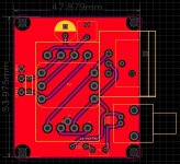
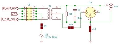
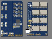
Example pcb audio transformer boart, port from dsc2.6.2 pcb, might help you get our pcb working, but if you not like the size of the pcb do your own audio trnsformer pcb design or even your own i/v preamp frontend which not use transformers at all, thats why I not included this on main pcb. : )
It accept LL1527XL transformer and also this one https://it.aliexpress.com/item/32810421236.html , one xlr connector NC3MAH-0 and one rca connector from Elecaudio er-106
It accept LL1527XL transformer and also this one https://it.aliexpress.com/item/32810421236.html , one xlr connector NC3MAH-0 and one rca connector from Elecaudio er-106
Attachments
Last edited:
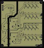
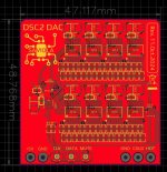
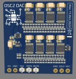
For those who looking for vertical mount mono dsc2, without isolation and without power supply. Pcb dimension 49x47 mm
I'm included u_fl coaxial connectors for DSD digital-in because of easier routing on main pcb.
I'm included u_fl coaxial connectors for DSD digital-in because of easier routing on main pcb.
Attachments
I still have this one which I made year-two ago https://www.diyaudio.com/community/attachments/img_2130-jpg.1117507/ and not tried them. Idea was using dsp with our dsc2 this way: ct7302 for conversion to PCM, and another one for conversion to DSD, between those two ct7302 plan was to put adau1462, thats nice idea but never tried : ( Our small vertical dsc2 is good for this test, probably I will make one main pcb and also one vertical dsp module, and will do one ct7302 pcb also for vertical mount, and probably clock board vertical too with LMK05318B , those things I must try next. I'm working also on ct7601, those ic is amazing, I'm realised that it have internal mcu which can be used as a master mcu for things, very nice usb bridge!
My i/v is active, and I want back to audio transformers, it sound way better than any active frontend in no dout while using dsc2, but I wanted tone control and thats the only reason why I switched to active frontend, now if I want audio transformers and tone control than I must do something, and I will do some pcb here in relation to ct7302, ct7601, adau1462 and clock board. And will need also some sugestions in relation to clock board, booth ct7302 and cp7601 can be configured for two clock mode, 12Mhz and 12.288MHz, and adau1462 need 12.288MHz, it would be nice making some software trigers for clock switching and I think the good candidate for master clock is LMK05318B on which we can fine set all the needed frequencies? The idea for using vertical mount pcb and u_fl I think is the easiest for inerconnecting all the things together?
My i/v is active, and I want back to audio transformers, it sound way better than any active frontend in no dout while using dsc2, but I wanted tone control and thats the only reason why I switched to active frontend, now if I want audio transformers and tone control than I must do something, and I will do some pcb here in relation to ct7302, ct7601, adau1462 and clock board. And will need also some sugestions in relation to clock board, booth ct7302 and cp7601 can be configured for two clock mode, 12Mhz and 12.288MHz, and adau1462 need 12.288MHz, it would be nice making some software trigers for clock switching and I think the good candidate for master clock is LMK05318B on which we can fine set all the needed frequencies? The idea for using vertical mount pcb and u_fl I think is the easiest for inerconnecting all the things together?
Last edited:
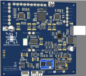
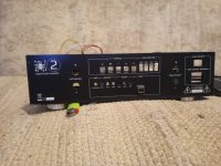
This was my first atempt but I never populated pcb. It have BT, FM, two ct7602, adau1462, ct7601 with isolator, 4 optical in, optical out,... it was waste off time, I was not satisfied with layout and it was time when I not practiced star gnd, instead gnd was not canaled and not under control and it will not work satisfactory.I think better idea is making all the sections on their own vertical pcb, modular? And this time with controled gnd.
Attachments
Last edited:
Hmm I'm searching LCSC for part number of this https://www.aliexpress.com/item/1005001351112758.html but can't get it on lcsc, anybody know the part number on LCSC? This will be recommend for our modular pcbs
This one https://www.ti.com/lit/ds/symlink/lmk05318b.pdf is nice one, status registers with interupts is hm very suitable for adding an gps module to the same modular pcb for gps sinhchronisation, hat would be an nice master clock module? : )
Almost finished this https://www.diyaudio.com/community/threads/signalyst-dsc1.254935/post-7791824 , and almost to test it found one bug, my current digi relay pot is latching and I was make non latching driver, clickclick click and it stopped to click omg! : ) Today designed latching driver and whole new concept for the same pot with the same pcb size, its much better than non latching! : )
pcb 30x50mm for modular mount. There is 4 x pcb, two for bass, two for treble. With 7 steps linear mode the same as normal analog linear pot. This is for my tone control in dsc2 frontend.
pcb 30x50mm for modular mount. There is 4 x pcb, two for bass, two for treble. With 7 steps linear mode the same as normal analog linear pot. This is for my tone control in dsc2 frontend.
Attachments
Last edited:
Backside for this https://www.diyaudio.com/community/threads/signalyst-dsc1.254935/post-7791768 done, and also new relay digipot pcbs with latching relay driver.
Attachments
Regarding modular design I got one idea about master clock pcb. This is based on an bangap voltage reference ic which also provides an output voltage that varies linearly with temperature, from 500mV to 620mV on that pin, allowing the part to be configured as a temperature transducer while providing astable voltage reference, putting it itself into an copper enclosure might give booth oven controled voltage reference and an SC cut cristal under stable temperature! Simulation result:

Now this is an precise oven for temperature control and now we have oven controled voltage reference for e.g. an J.D. reguilators and also temperature stabilised SC cut cristal. But what is a driver for crystal? Hmm. My idea is to sacrifice one piece CT7302 for purpose to become crystal driver! CT have dynamic range 190db and an THD+N -175db which is amazing and CT also have their mclk out (TTL compatible) and I expect that it give an nice and stable mclk now because now we have stabilised temperature on SC cut crystal. The next is what we can do with that mclk. But we don't know its precise exact frequency, we don't know its precise temperature because we do not have equipment to measure that. But we know for sure that it will stabilise at a certain temperature that will be very stable and we know that this frequency will not vary because oven is settled up to an stable temperature, and we know freq will be somewhere around 10MHz. So what now to get an known freq? My idea is putting now that stable ref clock to https://www.ti.com/lit/ds/symlink/lmk05318b.pdf and also its possible to add some gps module for 1ppm gps synchronisation, and also an mcu from which we sinhronise our master clock outs from LMK to an fixed frequencies. It might be very stable and almost no jiter and very good phase feature. So this migh become gps disciplined oven controled multifreq XO with voltage reference. What is your opinion about idea?? : )
Now this is an precise oven for temperature control and now we have oven controled voltage reference for e.g. an J.D. reguilators and also temperature stabilised SC cut cristal. But what is a driver for crystal? Hmm. My idea is to sacrifice one piece CT7302 for purpose to become crystal driver! CT have dynamic range 190db and an THD+N -175db which is amazing and CT also have their mclk out (TTL compatible) and I expect that it give an nice and stable mclk now because now we have stabilised temperature on SC cut crystal. The next is what we can do with that mclk. But we don't know its precise exact frequency, we don't know its precise temperature because we do not have equipment to measure that. But we know for sure that it will stabilise at a certain temperature that will be very stable and we know that this frequency will not vary because oven is settled up to an stable temperature, and we know freq will be somewhere around 10MHz. So what now to get an known freq? My idea is putting now that stable ref clock to https://www.ti.com/lit/ds/symlink/lmk05318b.pdf and also its possible to add some gps module for 1ppm gps synchronisation, and also an mcu from which we sinhronise our master clock outs from LMK to an fixed frequencies. It might be very stable and almost no jiter and very good phase feature. So this migh become gps disciplined oven controled multifreq XO with voltage reference. What is your opinion about idea?? : )
Last edited:
Ah done this -> https://www.diyaudio.com/community/threads/isolated-dsc2-dac.418617/post-7823587 The funy part of these relays is their sound, its sound like gun from super mario bros when moving pot value : )
- Home
- Source & Line
- Digital Line Level
- Isolated DSC2 DAC