The original 'isobaric' compound driver enclosure was done by RCA.
It used an internal 12" driver behind the external 15" driver. A very small metal tunnel mounted the internal driver behind the larger external driver, the magnet for the external driver was nested in the front of the internal driver.
The drivers were wired in series, and their impedance was adjusted to make them work properly.
The best modern implementation of this idea would be to use a high excursion smaller driver behind a large high efficiency driver on the outside. A plate amp could drive the internal driver, and make level matching easy.
Last edited:
My experiment with (so-called) "Frankenstein" Isobaric Driver Arrangement
Here's the promised (& overdue - sigh!) synopsis of my recent investigation into the feasibility of using similar - but not identical - loudspeakers in Isobaric arrangement.
First, a bit of background on this project:
I'm making a stereo set of speakers to be installed at a friend's cabin. They will be built-in to the ceiling over an outdoor deck. That ceiling consists of open timber joists (nominal 2x10", on 16" centres) supporting another floor above. They will be driven as extension speakers from an older receiver/amplifier indoors. So, the installation dictates that enclosure volume and speaker baffle size are limited, they will be exposed to outdoor environment, and they should be 8 ohms. Finally (& sadly), there is always an increased risk of theft at this remote location, so I want to keep them as unobtrusive and undesirable to steal as possible, and hence also low cost. Of the various speaker components on hand, these 2 pairs of old 6"x9" car audio speakers seemed the best fit for the job. Typical of car audio, they are 4 ohms each. I considered running a pair of them wired in series for each side, but this of course presents problems with the enclosure design. Isobaric arrangement seemed an interesting option, but the enclosure design programs that I'm familiar with (WinISD & Hornresp) - while they do accommodate isobaric driver arrangement, don't appear capable of handling either non-identical or series-connected drivers. To solve this problem, I thought that if I could combine the parameters of two different (non-identical) drivers mounted in isobaric arrangement, the result could be plugged into the software to look like a single driver and allow me to easily design an enclosure for that.
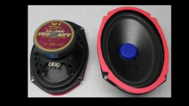
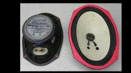
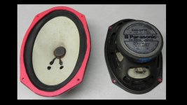
Some notes about the woofers: Both of the two pairs of speakers were originally multi-way coaxial, but I was happy to remove the H.F. components from them. I'm guessing they date back to around 1980, and have served in several vehicles over their life so far. The Panasonic pair is itself slightly mis-matched: PAN-I is Model EAB-940, while PAN-II is Model EAB-940N. The H.F. components were mounted on a "bridge" moulded integrally with the plastic frame, which I managed to completely detach. (One plastic frame was used as a spacer for the PAN-I/PAN-II Isobaric test.) These woofers have a paper cone and treated fabric surround. The Lear Jet XL-693 speakers (LJ-I & LJ-II) are visually identical. Their H.F. components were mounted on a post screwed on through the motor centre pole, with a foam sealing ring. Removal of these bits meant I had to install a replacement dust cap on the centre of the cone, and install a screen on the opening in the back plate where the screw was removed. The plastic frames were left on these, for fear of damaging the woofer surrounds. The Lear Jet speakers have poly(propylene?) cones and intact(!) foam surrounds. (Incidentally - I've never seen foam surrounds that lasted that long, and in some quite extreme operating environment at that!)
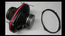
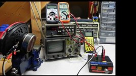
Measurement of the speaker parameters was done on a typical impedance jig, using the added mass method, and with applicable instrumentation. For each test, I established a minimum defining set of values comprising: Qes, Qms, Mms, Cms, Re, Le, fLe, & Sd. Xmax & Xlim were just estimated - ok since these are not highly relevant to my enclosure design anyway; and Pe was also an estimate based on the nameplate ratings. These "independent variables" (shown in cells with green background in my spreadsheet) were then input into the Driver Editor of WinISD to obtain all the other "dependent variable" parameters of interest. The latter were transcribed back to my spreadsheet (shown in cells with yellow background).
View attachment Speaker Parameters for Isobaric Investigation.pdf
The above measurement process was carried out first for each of the 4 speakers separately, and then for each possible combination of the 4 in isobarically mounted pairs, for a total of 10 tests. (The isobaric pairs were mounted face-to-face & connected in series in opposite phase, for correct push-pull cone motion.) All the parameters are summarized in the attached .pdf. To complete the analysis, I proposed (very simple & intuitive) algorithms to combine the parameters of each driver in an isobaric pair into single values for the assembly. (I chose the set of minimum defining parameters as listed above.)
My proposed combining algorithms ( for arbitrary drivers [1] & [2] combined to assembly [A] ) were:
Sd - average the two values: Sd[A] = ( Sd[1] + Sd[2] ) / 2
Re - add the two values for series connection, taking into account the test lead & jumper Resistance: Re[A] = Re[1] + Re[2] - Rtest-leads + Rjumper
Le - add the two values for series connection: Le[A] = Le[1] + Le[2]
Qes & Qms - average the two values for each: Qes[A] = ( Qes[1] + Qes[2] ) / 2 ; Qms[A] = ( Qms[1] + Qms[2] ) / 2
Mms - add the two values: Mms[A] = Mms[1] + Mms[2]
Cms - reciprocal sum the two values: Cms[A] = 1 / ( 1 / Cms[1] + 1 / Cms[2] )
Notes:
1) Since the remaining parameters can be derived from those given above, it follows that algorithms could be proposed to similarly combine them. As well, the calculations for Re & Le could also be easily modified for drivers electrically connected in parallel.
2) It is apparent that the combined mass of the air load: Mmr[A] on an isobaric assembly is not exactly equal to Mmr[1] + Mmr[2], so a correction should really be applied to the calculation of Mms[A]. I didn't do that in my experiment, only because I'm still unclear on how to quantify that.
3) I would suggest that volume displacement of the two drivers (Sd x Xmax) should be similar; if they are not, then I'd suspect that the driver with the lower value of that would dictate the performance limit of the Isobaric assembly. I.e. - it might be feasible to use a larger driver with smaller Xmax together with a smaller driver having larger Xmax. I didn't do a rigorous calculation of those parameters in my experiment, since Xmax was just a rough estimate - not measured.
I then calculated a "Predicted" value for each independent variable of each isobaric pair arrangement, and compared those to the values determined by test measurement. You can see the correlations from the Isobaric Summary Sheet (page 3 of the .pdf): Values for Re & Le were within 2%, Qms within 5%, Cms within 6%, Qes within 9%, and Mms within 11%.
To conclude, I've shown that it is possible to predict the parameters of an isobarically-mounted pair of non-identical drivers with reasonable accuracy. In my view, this could be useful for preliminary assessment & selection of candidate drivers, but of course, actual test measurements of the final configuration is highly preferable for good accuracy. I would also suspect - as others have already pointed out in this discussion - that there may be no widely useful purpose for the whole concept, other than - as in my described application - to make use of some existing non-identical drivers on hand. I do question whether there's any performance gain to be had, but I leave that research to others (at least for the time being...) In the case of this specific project, I feel that I've found the best arrangement of the drivers on hand for the purpose. (It looks like LJ-I / PAN-II, and LJ-II / PAN-I gives the best matching pair, so that's what I will use as a basis of my enclosure design.) On the other hand, I would have no hesitation to use the process of combining parameters of two of the same driver to a single isobaric assembly for use in software that doesn't support that (i.e., no way to input series-connected isobaric drivers, etc.). The question of more accurate calculation of Mms[A] remains, but that would of course be resolved by test measurements of the actual assembled driver pair.
Well, I hope this is at least of passing interest to a few members out there. Looking forward to any comments/questions!
Wilf
Here's the promised (& overdue - sigh!) synopsis of my recent investigation into the feasibility of using similar - but not identical - loudspeakers in Isobaric arrangement.
First, a bit of background on this project:
I'm making a stereo set of speakers to be installed at a friend's cabin. They will be built-in to the ceiling over an outdoor deck. That ceiling consists of open timber joists (nominal 2x10", on 16" centres) supporting another floor above. They will be driven as extension speakers from an older receiver/amplifier indoors. So, the installation dictates that enclosure volume and speaker baffle size are limited, they will be exposed to outdoor environment, and they should be 8 ohms. Finally (& sadly), there is always an increased risk of theft at this remote location, so I want to keep them as unobtrusive and undesirable to steal as possible, and hence also low cost. Of the various speaker components on hand, these 2 pairs of old 6"x9" car audio speakers seemed the best fit for the job. Typical of car audio, they are 4 ohms each. I considered running a pair of them wired in series for each side, but this of course presents problems with the enclosure design. Isobaric arrangement seemed an interesting option, but the enclosure design programs that I'm familiar with (WinISD & Hornresp) - while they do accommodate isobaric driver arrangement, don't appear capable of handling either non-identical or series-connected drivers. To solve this problem, I thought that if I could combine the parameters of two different (non-identical) drivers mounted in isobaric arrangement, the result could be plugged into the software to look like a single driver and allow me to easily design an enclosure for that.


Some notes about the woofers: Both of the two pairs of speakers were originally multi-way coaxial, but I was happy to remove the H.F. components from them. I'm guessing they date back to around 1980, and have served in several vehicles over their life so far. The Panasonic pair is itself slightly mis-matched: PAN-I is Model EAB-940, while PAN-II is Model EAB-940N. The H.F. components were mounted on a "bridge" moulded integrally with the plastic frame, which I managed to completely detach. (One plastic frame was used as a spacer for the PAN-I/PAN-II Isobaric test.) These woofers have a paper cone and treated fabric surround. The Lear Jet XL-693 speakers (LJ-I & LJ-II) are visually identical. Their H.F. components were mounted on a post screwed on through the motor centre pole, with a foam sealing ring. Removal of these bits meant I had to install a replacement dust cap on the centre of the cone, and install a screen on the opening in the back plate where the screw was removed. The plastic frames were left on these, for fear of damaging the woofer surrounds. The Lear Jet speakers have poly(propylene?) cones and intact(!) foam surrounds. (Incidentally - I've never seen foam surrounds that lasted that long, and in some quite extreme operating environment at that!)


Measurement of the speaker parameters was done on a typical impedance jig, using the added mass method, and with applicable instrumentation. For each test, I established a minimum defining set of values comprising: Qes, Qms, Mms, Cms, Re, Le, fLe, & Sd. Xmax & Xlim were just estimated - ok since these are not highly relevant to my enclosure design anyway; and Pe was also an estimate based on the nameplate ratings. These "independent variables" (shown in cells with green background in my spreadsheet) were then input into the Driver Editor of WinISD to obtain all the other "dependent variable" parameters of interest. The latter were transcribed back to my spreadsheet (shown in cells with yellow background).
View attachment Speaker Parameters for Isobaric Investigation.pdf
The above measurement process was carried out first for each of the 4 speakers separately, and then for each possible combination of the 4 in isobarically mounted pairs, for a total of 10 tests. (The isobaric pairs were mounted face-to-face & connected in series in opposite phase, for correct push-pull cone motion.) All the parameters are summarized in the attached .pdf. To complete the analysis, I proposed (very simple & intuitive) algorithms to combine the parameters of each driver in an isobaric pair into single values for the assembly. (I chose the set of minimum defining parameters as listed above.)
My proposed combining algorithms ( for arbitrary drivers [1] & [2] combined to assembly [A] ) were:
Sd - average the two values: Sd[A] = ( Sd[1] + Sd[2] ) / 2
Re - add the two values for series connection, taking into account the test lead & jumper Resistance: Re[A] = Re[1] + Re[2] - Rtest-leads + Rjumper
Le - add the two values for series connection: Le[A] = Le[1] + Le[2]
Qes & Qms - average the two values for each: Qes[A] = ( Qes[1] + Qes[2] ) / 2 ; Qms[A] = ( Qms[1] + Qms[2] ) / 2
Mms - add the two values: Mms[A] = Mms[1] + Mms[2]
Cms - reciprocal sum the two values: Cms[A] = 1 / ( 1 / Cms[1] + 1 / Cms[2] )
Notes:
1) Since the remaining parameters can be derived from those given above, it follows that algorithms could be proposed to similarly combine them. As well, the calculations for Re & Le could also be easily modified for drivers electrically connected in parallel.
2) It is apparent that the combined mass of the air load: Mmr[A] on an isobaric assembly is not exactly equal to Mmr[1] + Mmr[2], so a correction should really be applied to the calculation of Mms[A]. I didn't do that in my experiment, only because I'm still unclear on how to quantify that.
3) I would suggest that volume displacement of the two drivers (Sd x Xmax) should be similar; if they are not, then I'd suspect that the driver with the lower value of that would dictate the performance limit of the Isobaric assembly. I.e. - it might be feasible to use a larger driver with smaller Xmax together with a smaller driver having larger Xmax. I didn't do a rigorous calculation of those parameters in my experiment, since Xmax was just a rough estimate - not measured.
I then calculated a "Predicted" value for each independent variable of each isobaric pair arrangement, and compared those to the values determined by test measurement. You can see the correlations from the Isobaric Summary Sheet (page 3 of the .pdf): Values for Re & Le were within 2%, Qms within 5%, Cms within 6%, Qes within 9%, and Mms within 11%.
To conclude, I've shown that it is possible to predict the parameters of an isobarically-mounted pair of non-identical drivers with reasonable accuracy. In my view, this could be useful for preliminary assessment & selection of candidate drivers, but of course, actual test measurements of the final configuration is highly preferable for good accuracy. I would also suspect - as others have already pointed out in this discussion - that there may be no widely useful purpose for the whole concept, other than - as in my described application - to make use of some existing non-identical drivers on hand. I do question whether there's any performance gain to be had, but I leave that research to others (at least for the time being...) In the case of this specific project, I feel that I've found the best arrangement of the drivers on hand for the purpose. (It looks like LJ-I / PAN-II, and LJ-II / PAN-I gives the best matching pair, so that's what I will use as a basis of my enclosure design.) On the other hand, I would have no hesitation to use the process of combining parameters of two of the same driver to a single isobaric assembly for use in software that doesn't support that (i.e., no way to input series-connected isobaric drivers, etc.). The question of more accurate calculation of Mms[A] remains, but that would of course be resolved by test measurements of the actual assembled driver pair.
Well, I hope this is at least of passing interest to a few members out there. Looking forward to any comments/questions!
Wilf
- Status
- Not open for further replies.