ISO "Simplest" possible amplifier
I'm in a minimalist phase. Can you fine folks suggest ideas for the "simplest" possible amp, with simple defined as:
- lowest parts count
- transistor based
- semi to marginally decent performance
- wall wart power
- 2 to 8 watts
Thanks!
-dano
www.beavisaudio.com
I'm in a minimalist phase. Can you fine folks suggest ideas for the "simplest" possible amp, with simple defined as:
- lowest parts count
- transistor based
- semi to marginally decent performance
- wall wart power
- 2 to 8 watts
Thanks!
-dano
www.beavisaudio.com
Thanks guys, I'll give those a look.
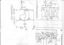
In the meantime, I came across this schematic:
I've built it up, but no sound. The notes say to bias at 1/2 of Vcc at the drain of Q1, but I can get nowhere near that. I can adjust the trimmer to get 1/2 Vcc at the gate...
Any ideas on what I've done wrong?
In the meantime, I came across this schematic:
An externally hosted image should be here but it was not working when we last tested it.
I've built it up, but no sound. The notes say to bias at 1/2 of Vcc at the drain of Q1, but I can get nowhere near that. I can adjust the trimmer to get 1/2 Vcc at the gate...
Any ideas on what I've done wrong?
The trimpot supplies the gate with any voltage between ground and full power supply voltage. So if you can´t find the DC operating point there and can verify that the gate voltage really moves I´d say there is only two more components that can be faulty, the FET or the 50 ohm load resistor.
The resistor can be measured very simply, and if it´s ok it has to be a blown FET. They go S/C, so the resistor should become hot if this is the case.
🙂
The resistor can be measured very simply, and if it´s ok it has to be a blown FET. They go S/C, so the resistor should become hot if this is the case.
🙂
Turn C1 around. It is a bad solution to use it with its positive side to the left and charge it on its negative side on the right through R1 with +9..+28 V.dano12 said:Any ideas on what I've done wrong?
The input high-pass f3 is 1 / (2*pi*R1*C1). With R1 set to maximum (10k) you get a nice 1,6 Hz high-pass. With R1 set near minimum (e. g. 1 Ohm) the f3 point will be 16000 Hz. Not much left to hear, if everything below 16 kHz is filtered out.
You were probably trying to build this amplifier?
Thanks for the ideas. I checked the resistor and it is good.
I guess I should have socketed the FET (argh)
I'll try reversing the capacitor and putting in a new FET.
Thanks again.
I guess I should have socketed the FET (argh)
An externally hosted image should be here but it was not working when we last tested it.
I'll try reversing the capacitor and putting in a new FET.
Thanks again.
What's your Vcc?
This FET is rated 20V max Vgs. If you're using the 28V Vcc, and you start with the pot turned all the way up, you'll blow the gate first thing.
This FET is rated 20V max Vgs. If you're using the 28V Vcc, and you start with the pot turned all the way up, you'll blow the gate first thing.
I just wanted to point out that that metal power resistor is
suposed to be mounted on a big heatsink.
suposed to be mounted on a big heatsink.
if thats a pic of your amp id also say that even for testing, the fet heat sink is way, WAY, to small.
bigger ones are easy to find in old pc's and and the power supply's of old pc's. (make sure they are safely earthed out first)
nice though, hope you get it working, steve.
bigger ones are easy to find in old pc's and and the power supply's of old pc's. (make sure they are safely earthed out first)
nice though, hope you get it working, steve.
Dano,
I built a small amp similar to this one and it worked just fine on 9v to 12v, but not terribly loud.
I would suggest that R1 be changed 100k or even 1M. Also the C1 input capacitor needs to be turned around so the plus side is to the mosfet.
When used with 9v, mine did not get hot enough that a heat sink was even necessary, though I did not drive it hard for long periods.
regards, Jack
http://www.muzique.com/
I´ve built a couple of amps quite similar to the one in post 3 and with the right speakers this topology has some nice features.
(fullrange drivers sometimes sounds better mated with high Zout amps).
Driving the Mosfets input capacitance requires and active preamp though.
(fullrange drivers sometimes sounds better mated with high Zout amps).
Driving the Mosfets input capacitance requires and active preamp though.
"Any ideas on what I've done wrong?"
You don't have a schematic that's useable.
130mA?
If R2 was an active current source, then 130mA of bias would be 0.092 mA into an 8 ohm speaker. (I^2)R=0.067W
67milliwatts.
Throw away this schematic.
Read this:
http://www.passdiy.com/pdf/zenamp.pdf
Circuit board here:
http://www.audioxpress.com/bksprods/products/pcbp-11.htm
Thanks guys for all the advice.
Turned out that I hadn't properly grounded the source of the FET (doh!). After doing that it fires up fine.
I'm running it at 18 volts, the FET barely gets warm but the 50 ohm resistor get's very hot. I'll take the recommendation and remount it on a heat sink.
Jack, thanks for the ideas. I actually used your excellent MOSFET boost as a preamp.
I'll reverse the cap and do some more tinkering tonight.
If you are running it at 18v you could replace that 50 ohm
resistor with a 12v turn signal light bulb.
What are you using as a input source? If your input source
is a something like a cd or sound card you might get better
results with these componints using them in a source follower.
resistor with a 12v turn signal light bulb.
What are you using as a input source? If your input source
is a something like a cd or sound card you might get better
results with these componints using them in a source follower.
As far as I'm concerned, mission accomplished with this one. I fashioned a hillbilly heatsink for the power resistor, stuck a single transistor pre-amp in front of it, stuck it in a computer CDROM cage and called it a day.
It makes a nice little guitar amp, drives an 8 ohm cab very well.
I think now I'll move on to some of the better suggestions posted here.
Thanks again for the pointers!
An externally hosted image should be here but it was not working when we last tested it.
It makes a nice little guitar amp, drives an 8 ohm cab very well.
I think now I'll move on to some of the better suggestions posted here.
Thanks again for the pointers!
If you replace the resistor with an LM317 regulator it will double the efficiency of the amplifier, and double the output power, and the regulator will probably cost less than the resistor.
dano12 said:... I fashioned a hillbilly heatsink for the power resistor, stuck a single transistor pre-amp in front of it, stuck it in a computer CDROM cage and called it a day
That is the coolest piece of crXp I've ever seen on DIY! I want one just like it STAT. 😎
- Status
- Not open for further replies.
- Home
- Amplifiers
- Solid State
- ISO "Simplest" possible amplifier