It took me some time to do this mod due to other projects but now it is done and working! The 494 that had a max voltage of 2kv @ 90 mA now has been modified and gives 0-1200V @ 300mA. If something fails, uncontrolled voltage will not exceed 1300V under no load. It can also work at limited current settings as the 600V scale current control knob is still functioning.
Another mod in progress is to silence the humming transformer, almost done.
Anyone interested in the mod procedure can ask me for detailed instructions.
This will become a great GM70 211 845 etc power supply!
Another mod in progress is to silence the humming transformer, almost done.
Anyone interested in the mod procedure can ask me for detailed instructions.
This will become a great GM70 211 845 etc power supply!
Nice I have a surplus Bio-Rad SDS-Page gel PSU. It is listed as capable of 500V@ 200mA. Has a bunch of nice caps in it to (SPraque Powerlytic, Sprague atom, loads of CDE, a huge TO-3 heatsink on the back, etc.)
I am likely gonna take it apart and make something out of the case. Considering trying to make a small computer with built in headphone amp (and maybe a small amp for powering a small set of speakers).
I am likely gonna take it apart and make something out of the case. Considering trying to make a small computer with built in headphone amp (and maybe a small amp for powering a small set of speakers).
Last edited:
ISCO 494 ELECTROPHORESIS modification procedure by adam2a3 (SV1CDU)
Original spec of 0-2000V @ 90mA will become 0-1250V @ 290mA max.
1.Remove C25, C26, C28, C23 (a pair of terminal lugs carrying 47K resistors will be removed too)
2. On the pcb, solder a piece of wire between terminals of C28.
Same between terminals of C23
3. Cut/remove diodes CR30, CR31, CR39, CR31 and SHORT CR37 and CR35
4. Cut the following cables at a distance of 1 inch from the pcb
CUT: 29 blue, 33 yel, 28 red, 36 grey, 37 purple
5. Connect 36 grey to 37 purple (the 1 inch parts, coming out from pcb)
6. Connect 29 blue to 33 yellow (the 1 inch parts, coming out from pcb)
7. Insulate all exposed cable ends using heatshrink tubing (8 places in total)
8. Short R66=66 Ohm 11W by soldering a small wire underneath. You may remove this resistor or just leave it in place..
9. Similarly for R59
10.Replace R150=469K by a 820K 0.5W
11. Unsolder one side of R154=66K , Connect a 12 K 1/4W to the lifted lead and it’s other end to the pcb. Now R154 will become (66+12) K
12. Remove R62 and R63 (both 47K 11W).
13. RECHECK EVERYTHING
14.Connect a DVM having a max 1000Vdc scale to the HV black/white terminals
14.Adjust watts and current knobs to 100%, voltage to zero. Power on.
15. Turn up the voltage knob to 800V as read on the ISCO panel meter.
16. If the dvm shows a different voltage, adjust R100 until dvm reads 800V.
17. Power off, remove dvm, connect the dummy load at the hv terminals, (mine is 3980 Ohms @ 200W), set Voltage knob close to zero, turn the center knob to 600V 300mA, and power on again.
18. Set Voltage knob to 100%. Adjust R149 for 1250V at the panel meter, and V light just coming on.
19. Set Current knob to 100%. Adjust R153 until a current of almost 300mA is observed on the right panel meter and mA light just comes on.
20. Multiply V and mA and after turning selector to Watts, check reading on left panel meter. Adjust if needed R164 until correct power is shown.
By the above mod, the positive and negative triplers become doublers so max voltage is reduced. At the same time more mA’s become available. All current values shown on the limiter knob in 2 scales (600 and 2000V) now are still valid except that voltage is always 0-1250V. So by setting it at 600V 300mA we get 0-1250V 290mA. Before this mode you may measure voltages accros big electrolytics while unit is set to 2KV. Those caps that have low voltages usually are the leaky ones, so can be removed. 4 caps will be removed and become spares after the mode, allowing for swaps.
Good Luck!
ISCO 494 MOD typo correction
Please correct step 19, the trim pot for current limit adjustment is R145 (not
R153 that adjust Watts limit).
TRANSFORMER POTTING
If you are going to use this supply in the listening room, you will notice that the transformer is very noisy. This is the procedure to make it dead quiet.
1. Cut all transformer cables going to pcb leaving 1cm at the pcb side to locate the soldering point easily later on.
2. Unscrew all transformer cables from mains terminal strip, after attaching stickers with numbers and taking notes of their positions.
3. Remove the U bracket that connects the front and rear panel and also supports the transformer. Remove the transformer. The white cylinders supporting it's front legs will stay on the pcb. Do not remove them.
4. Turn the unit upside down, rear panel facing you. Hold it like this in a big vice, that can press only the rear panel's first 2-3cm. Target: to drill holes at the rear panel. Do not use other orientation as debris can fall and remain on the pcb.
5. Take the aluminum square plate that was at the back of transformer and one silver or gold marker. Use it as a template. Mark 4 drilling points for the new position of the transformer, that will be 1 cm to the right and 0.5cm lower compared with the original positioning. This will lead the transformer 1 cm further away from the big electrolytics and 0.5cm higher from the board. You will see why soon.
6. Drill another 4 holes, right on the previous mounting screws, to destroy and remove them. Alternatively you may cut them flush. Will not be needed.
7. All holes will be 4mm, so 4 new screws approx 3cm long must be secured by a nut and washer at each transformer foot, head facing towards coils. Tighten them as the head will not be accessible later on, as the transf will be potted.
8.Using a piece 5 mm thick plywood, construct a cubic box where the transformer must fit. No upper cover needed. Make it touching the core. Use glue and staple each corner. Drill 4 holes for the transf screws. The next day put the transf inside, and secure all cables upwards and out of the box. Attach the metal plate OUTSIDE the wooden box and tighten it with nuts to hold transf in position.
9. For potting material use semi rigid tar, it comes in 5kgr cans and is used for roof isolations. This is VERY sticky, adheres to anything and creates a mess (black).
CAUTION:
If you are married the following steps must be followed when your wife is not at home!
10. Use an old pan to melt the tar. (best performed outdoors or the room will have a tar smell for several hours) Do not melt the full quantity needed, just repeat steps 10-11.
11. Very carefully (HOT!) pour the melted tar in the wooden box until it's surface just covers the core. No problem if the core is visible.
12. After some hours, you may reassemble the transfomer but before this, all leads must be lengthened. Start from the pcb side, that will not be easily accessible later.
13. The square metal plate goes on the outside of unit's case and transf is secured by nuts and lock washers from the outside.
14 The mains terminal strip must be relocated. I use only half of it.
15 Note that 2 transformer cable pairs are not needed to go to the board again and are jumpered directly (blue+orange) and white+brown in 220V configuration.
The U bracket will not be reassembled and the transf will just rest on the white plastic cylinders. So do not drop the unit!
16. This mod will make the transf VERY quiet. Good luck with tar melting!
Hi,
Nice work, but i have been thinking in the mods and regarding the STEP 3 why shunt cr35 what is the point? maybe the cr38 would be shunted, you also wrote to remove cr31 twice...or must be the cr41 to be removed; STEP 2 why remove c28 and c23 and shunt their respectiv terminals.
See the schematic above.
All the best Luis
Attachments
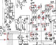
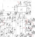
TYPO CORRECTION of STEP 3 in ISCO mod procedure
Hi Luis, nice observations, indeed on STEP 3 diodes to be shunted are CR37, CR38 and to be cut/removed CR30,CR31,CR39,CR42 (not 41!)
But STEP 2 is correct, the voltage accross the series C23,C24 and C27,C28 respectively becomes half so it is a waste to keep them like this.Why not to double the capacitance and keep another 2 electrolytics as spares?
At the negative side of the output you may also connect a 15H 0.5A choke and then a nice oil capacitor, like 20uF@2kV. This is my configuration for one channel of a GM70pp amp.
For my personal GM70SE I will use chokes on both lines, an MKV Siemens cap or a defibrillator one and possibly a tube regulator.
Another step to my transformer silencing mod is to add blue elastic grommets on the 4 screws supporting the transformer box on the rear panel.
I noticed that buzz is transfered through the screws so this is a good solution.
A metal angle covered by a piece of rubber must also be placed below the transformer box to relief some of it's weight and prevent destruction of the grommets due to verical forces. The box rests also on the 2 white rods in the middle of the pcb, that are cut at 2/3 of their original length.These could be cut at 1/2 size and 2 pieces of rubber could added at the boxe's rest points. for additional isolation.
So far one pair is working fine here.
Bad electrolytics can explode, remove all of them and test them at 100 Volts while checking current. If you see more than 5-10mA and after some time are not getting reformed don't put them back!
Let me know about your progress if you do the mod.
Regards, adam2a3
Luis, are you located in Coimbra Portugal? I have been there last week! This morning I've been listening to "Coimbra" by Joao Farinha. It was performed live at a small scene on a street having a bronze statue of a woman holding a vase. I purchased the CD recording from that place.
Regards, adam2a3.
Regards, adam2a3.
Hi adam,
Sorry for delay, yes I am from Coimbra, well I see that you like Coimbra Fado's this is the traditional academic students music. i know very well the street, this is a small worl indeed") ))
))
regardind the isco psu i have a 495 it is well made, but the transformer when in charge is extremely noisy, I cannot find if it is a problem or not. I do not have the schematic so it is dificult to perform an extensive test. I contavt the teledyne company (Andrew and sent me a manual but it is useless because does not have the sch). you wrote that your trafo was very noisy, so I am not worry. I have some ripple 300v scale 0.7v RMS at 150ma 600scale with 500v 250ma : 3.2v 2000vscale with 650v 120ma 7v
The caps probably need be replaced, but this screwed caps are not cheap and they are 11 caps...Itested the psu with 4 h choke and solen 47uf cap and the riplle decrease for a few mv,but like I said the noisy is untolerable.
I buil a GM70PP amp based last year I will post some pictures here soon.
regards Luis
Sorry for delay, yes I am from Coimbra, well I see that you like Coimbra Fado's this is the traditional academic students music. i know very well the street, this is a small worl indeed
))regardind the isco psu i have a 495 it is well made, but the transformer when in charge is extremely noisy, I cannot find if it is a problem or not. I do not have the schematic so it is dificult to perform an extensive test. I contavt the teledyne company (Andrew and sent me a manual but it is useless because does not have the sch). you wrote that your trafo was very noisy, so I am not worry. I have some ripple 300v scale 0.7v RMS at 150ma 600scale with 500v 250ma : 3.2v 2000vscale with 650v 120ma 7v
The caps probably need be replaced, but this screwed caps are not cheap and they are 11 caps...Itested the psu with 4 h choke and solen 47uf cap and the riplle decrease for a few mv,but like I said the noisy is untolerable.
I buil a GM70PP amp based last year I will post some pictures here soon.
regards Luis
Silencing ISCO 494
Hi Luis,
I will also upload the schematics of my 6SN7 2XRY50 2XGM70 (Class A PP) amps powered by a pair (!) of modified ISCO 494 units, that are also silenced.
See my tar silencing mod here. The schematics can also be found easily in a thread here, just search for ISCO.
By the way, how can I upload photos?
Regards, adam2a3
- Status
- This old topic is closed. If you want to reopen this topic, contact a moderator using the "Report Post" button.
- Home
- Amplifiers
- Power Supplies
- ISCO 494 ELECTROPHORESIS modified to 1200V 300mA