y'all,
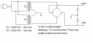
Look at this schematic and tell me if this is legal, safe, or otherwise just a bad idea. I have a couple of really nice 16v 5 amp torroids laying around, but they are not center tapped. I would like to make a bipolar 24v supply (after full wave rectification) and am wondering if this arrangement will do.
(Of course, I will have to pay attention to the polarity of the transformers), but what is the down side of connecting one of the legs of the output terminals together to form a common point for ground? I have never seen this method of providing a center tap from two single ended transformers anywhere on the internet and am just wondering if I am doing something illegal, fattening or immoral...
Attachments
No big deal, it will work.
Thanks, y'all!
Just make sure your matching is good, you might have to use trim/bleeder resistors. Many circuits using bipolar supplies rely upon supply matching for DC rejection, so if that's the case, you'll have the sum of the supply voltages (or thereabouts) on your output.
That's why I was askin... It's those little details I am blissfully ignorant of that I fear the most.
FYI, I actually took a couple 24 volt torroids and unwound the secondaries by hand and stopped unwinding when I got to 16 v. Hooked up, they are within 0.1 volt of each other and there is even a pot adjustment for the DC correction on the output.
Cheers,
Phil

I agree that two separate DC supplies removes most of the risks of getting it wrong.A better method is to use two full wave bridges with filter caps to make two dc supplies and then connect those. The method you show to create a center tapped transformer is subject to increased noise and lowered capacity if both rails are not loaded uniformly.
You started with two 120VA transformers. A single 240VA transformer is usually better than two 120VA.................I actually took a couple 24 volt torroids and unwound the secondaries by hand and stopped unwinding when I got to 16 v. Hooked up, they are within 0.1 volt of each other and there is even a pot adjustment for the DC correction on the output............
As a result of your modifications you have two 80VA transformers and the regulation that comes with low VA.
Had you bought the correct 16+16Vac 240VA transformer, the regulation would probably been around half of what you have ended up with.
Last edited:
A better method is to use two full wave bridges with filter caps to make two dc supplies and then connect those. The method you show to create a center tapped transformer is subject to increased noise and lowered capacity if both rails are not loaded uniformly.
This is true, and a very low asymmetry can make a toroid saturate. Not only long term average currents must be equal, but halfcycle-by-halfcycle. An extra rectifier bridge is not a big price for avoiding this problem.
I agree that two separate DC supplies removes most of the risks of getting it wrong.You started with two 120VA transformers. A single 240VA transformer is usually better than two 120VA.
As a result of your modifications you have two 80VA transformers and the regulation that comes with low VA.
Had you bought the correct 16+16Vac 240VA transformer, the regulation would probably been around half of what you have ended up with.
Ain't worried about them. They are what they are...I had them on the shelf for 30 years. Too late to take them back to the store for an exchange...

This is true, and a very low asymmetry can make a toroid saturate. Not only long term average currents must be equal, but halfcycle-by-halfcycle. An extra rectifier bridge is not a big price for avoiding this problem.
We Agree!
The output of a 115:16Vac transformer is dependent on the input voltage and the output loading.
because he has
because he has
his output voltage at low loading can be exceptionally high.As a result of your modifications you have two 80VA transformers and the regulation that comes with low VA.
Had you bought the correct 16+16Vac 240VA transformer, the regulation would probably been around half of what you have ended up with.
The output of a 115:16Vac transformer is dependent on the input voltage and the output loading.
because he has his output voltage at low loading can be exceptionally high.
Actually Hal is correct. My measured DC output without any load on a full wave bridge rectifier (with caps) is 1.414 times the ac input voltage. I can't imagine how you can get an exceptionally higher voltage unless you get a brief voltage spike from accidentally disconnecting the load on the transformer. Increasing the load would only lower the voltage below the unloaded condition.
Who's Hal. There is no poster on this Thread named Hal.
Oops! My bad.
My eyes are not that good at my age. Maybe I need some glasses. Frogeye said, "Hal" at the end of his post. I thought it was Hal's signature!
Duh!
Frogeye is stating the output based on converting 16Vac sinewave to the peak voltage of that same sinewave.
But, that is not the way AC to DC conversion works.
As I said and you quoted
Vout = Vpri/Vrating*Vsec when the load passes the rated output current.
When there is no output current, then Vout = Vpri/Vrating*Vsec*{1+regulation}
If regulation for two 80VA (with +33% removed) is 10% (reg could be >14%), then
Vout with 120Vin would be around 120/115*16*1.1 ~18.4Vac
Vpk is ~26Vpk Two 16Vac transformers with a bridge rectifier could be ~52Vdc
Subtract 1V to 1.4V from that to arrive at the DC across the smoothing capacitors and you get ±25.3Vdc to ±25.5Vdc.
Attach a load and the 16Vac to ±24Vdc shown in your post1 is actually quite close.
Simply applying sqrt(2) does not predict the DC accurately.
But, that is not the way AC to DC conversion works.
As I said and you quoted
Most of the time the output from a 16Vac transformer is not 16Vac.The output of a 115:16Vac transformer is dependent on the input voltage and the output loading.
Vout = Vpri/Vrating*Vsec when the load passes the rated output current.
When there is no output current, then Vout = Vpri/Vrating*Vsec*{1+regulation}
If regulation for two 80VA (with +33% removed) is 10% (reg could be >14%), then
Vout with 120Vin would be around 120/115*16*1.1 ~18.4Vac
Vpk is ~26Vpk Two 16Vac transformers with a bridge rectifier could be ~52Vdc
Subtract 1V to 1.4V from that to arrive at the DC across the smoothing capacitors and you get ±25.3Vdc to ±25.5Vdc.
Attach a load and the 16Vac to ±24Vdc shown in your post1 is actually quite close.
Simply applying sqrt(2) does not predict the DC accurately.
Last edited:
- Status
- This old topic is closed. If you want to reopen this topic, contact a moderator using the "Report Post" button.
- Home
- Amplifiers
- Power Supplies
- Is this transformer arrangement legal?