something is broken !
there is no exit route for current into the +ve pin, other than out through the -ve pin.
There is no ground pin. The +ve and -ve quiescent currents should be the same.
Look at the datasheet simple sch.
At quiescent all the signal pins should have zero currents in/out.
For easier reference I have posted the circuit diagram from an earlier post. The circuit overlay and traces on the copper side as seen from above can be seen via the link to the service manual given in post #1.
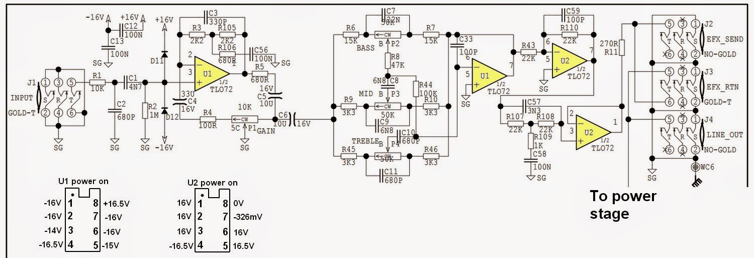
The IC supply current exiting issue is interesting since there is a positive voltage of 16.5 volts at U2 pin 5 a non-inverting input terminal which connects directly to signal ground and should measure zero volts. On the other hand U2 positive supply pin 8 registers zero volts instead of positive 16.5 volts.
Since circuit pins 3 and 5, the equivalent input terminals in the two circuit blocks in U1, both connect to signal ground, and if the positive 16.5 volts is a correct reading, it would be logical to see the same positive reading in those locations. Instead the readings are 14 and 15 volts negative respectively which puts that supposition in doubt.
There would appear to be a need to check these voltage readings and the continuity of the signal ground traces.
Last edited:
Since the circuit voltages are low, it is safe enough to try the moistened finger touch test to feel how hot U2 is in relation to U1.
Substituting an infrared thermometer for moistened finger I get the following after powering on for about an hour:
U1 73F / 22.8C
U2 82F / 27.8C
Readings elsewhere on the board were in the range 70-75F / 21-24C with the exception of R38 and R39 (shown in the service manual as part of the circuitry near the transformer and not on the preamp section I posted). The board under these components registered 104F / 40C. D9 and D10 flank these resistors. This was the warmest region on the board.
Thermography methods are not used in electronics, but an experienced tech can doubt a semi by touching his finger.
Gajanan Phadte
Gajanan Phadte
Two new TL072 and two new DIP8 sockets is quick, easy and cheap way to diagnose board fault or ic fault.
I would have had this item repaired by yesterday...🙄.
Dan.
I would have had this item repaired by yesterday...🙄.
Dan.
Substituting an infrared thermometer for moistened finger I get the following after powering on for about an hour:
U1 73F / 22.8C
U2 82F / 27.8C
Readings elsewhere on the board were in the range 70-75F / 21-24C with the exception of R38 and R39 (shown in the service manual as part of the circuitry near the transformer and not on the preamp section I posted). The board under these components registered 104F / 40C. D9 and D10 flank these resistors. This was the warmest region on the board.
I recommend doing a precautionary diode check on D9 and D10 after leaving the equipment turned off overnight. There is no picture to see however the service manual describes unmarked diodes as 1N4148 which are small signal diodes.
These are in series across C27 positive and C28 negative. The connection is in reverse polarity to the capacitors.
Under correct operating conditions R38 and R39 should be in the same temperature at R36 and R37. These pairs are part of the voltage regulator on opposite supply rails, negative and positive respectively.
If you measure the voltage drop across one of other of the opposites you can work out the current draw from Ohms law where I current (in amperes)=Volts/Resistance in Ohms.
Multiply the answer by 1000 to convert to milliamps to compare each rail to the range of current drawn by a TL072 - each internal amplifier is 1.4 - 2.5 milliamps. At the lower end that range with the temperatures you have measured - so the total drawn should be certainly less than 10 milliamps.
I think you will find the voltage drop across R38 or of R39 to be the greater.
U2 is running hotter than U1 and there is an internal path between the negative supply, pin 4 where the voltage is -16.5 and the positive supply, pin 8 which is at zero.
There are abnormal readings on other U2 pins, pin 5 being of particular concern since it connects to signal ground and the voltage should be zero.
The best way to remove an IC is to clip the leads sufficiently clear of the circuit board to leave something reasonable to grip with pliers. It is easier to de-solder and extract individual pins than a complete block of 8.
There is more of a risk of solder pads lifting because the IC might need to be levered out of the board and that is a messy process.
A 0.8 m.m. drill bit is useful to have to clear holes of any obstinate solder residue so there is clear path to fit a replacement part.
With the IC clipped out re- measure and note the voltages on the pins sticking out of the board.
With that done re-measure the pin voltages on U1 to see if these have altered. Apart from pins 4 and 8 these should be zero, critically pin 5 which connects to signal earth.
When it comes to replacing parts fitting 8 pin turned sockets to house the IC's will make servicing easier, since the IC's can be removed if that needs to be done in other areas inside the case. The odds are you will have to replace both U1 and U2 an assumption others have already made, however straight up I thought that might lead to disappointment for someone new to electronics should there be another hidden fault lurking elsewhere.
Last edited:
The flat pins of 8pin dips do not fit into turned pin sockets.
Oops. I visualized and meant the machined pin version.
Thanks for all the input. I especially appreciate the circuit testing information that helps me learn what is going on. Since my next step is removing the 2 ICs, the suggestion to clip them out and then remove the pins is timely. My real life job has been a bit hectic lately and is sucking time away from home projects, but I'll report back after I take the next steps.
IT WORKS!
Today I finally had the opportunity to clip out the old TL072s and install two sockets and ICs. I plugged in a guitar, turned on the amp and got nothing but single coil hum....until I remembered I had the guitar volume pot turned all the way down! You could have heard me howl a mile away when I turned up the pot and the amp started singing!
Thanks to all posters for your help, particularly mjona for explanations and Max for telling me to just get on with it.
Tom
Those look like turned pin sockets, fitted with dip opamps.
Could you show how they fit together?
Could you show how they fit together?
Those look like turned pin sockets, fitted with dip opamps.
Could you show how they fit together?
Turned pin sockets are preferred in the industrial world. They deform the IC pins slightly and wedge the pins in causing a better air tight connection than you would get with normal spring terminal connections but the same IC can't be reinserted repeatedly. Spring terminals will oxidize in the connection point fairly quickly causing connection problems. Turned pins take much longer to have the same issue.
I never tried to fit flat dip pins into a turned pin socket.
I used the spring clips version of the socket for dip. I stock both.
Whereas I use the turned pin for all other plug in round pins, as on transistors, caps, resistors, etc.
I also stock 14 & 16 pin sockets.
I steal the turned pin socket and solder the singles into a PCB that does not accept sil 0.1". This lets me try different input transistors for an LTP stage of a Power Amp.
It even lets me try a cascoded LTP where the PCB has provision for a simple two transistor LTP.
Congrats....happy times.IT WORKS!
LOL.......and Max for telling me to just get on with it.
Glad you got it going, you can now enjoy your new found repair skills 😉.
Dan.
Hmmm, turned pin DIP IC sockets have been available since forever for.....DIP ICs.I never tried to fit flat dip pins into a turned pin socket.
I used the spring clips version of the socket for dip. I stock both.
Whereas I use the turned pin for all other plug in round pins, as on transistors, caps, resistors, etc.
I also stock 14 & 16 pin sockets.
I steal the turned pin socket and solder the singles into a PCB that does not accept sil 0.1". This lets me try different input transistors for an LTP stage of a Power Amp.
It even lets me try a cascoded LTP where the PCB has provision for a simple two transistor LTP.
Turned pin sockets usually have gold plated contacts (not always) and are indeed the reliability preferred socket solution.
Spring clip DIP sockets are usually not gold plated and are cheaper, and do enable easier insertion.
Dan.
TLO82 is better/clearer put that in, /DIP socket and try a bunch etc, assuming you had an old TI Tl072 yeah they go bad. With different configuration's/loads/ 82 still came off to me as more clearer.
haven't tried the TLE2072 but I imagine it would be pretty good too as well as various Burr brown stuff.
haven't tried the TLE2072 but I imagine it would be pretty good too as well as various Burr brown stuff.
Last edited:
Op amp rolling/swapping is all well and good.....provided that the original pcb power routing/decoupling and earth routings are adequate/up to the task.TLO82 is better/clearer put that in, /DIP socket and try a bunch etc, assuming you had an old TI Tl072 yeah they go bad. With different configuration's/loads/ 82 still came off to me as more clearer.
haven't tried the TLE2072 but I imagine it would be pretty good too as well as various Burr brown stuff.
TL072 is quite benign and tolerates bad layouts to a degree.....newer/faster op amps may not tolerate sub optimal layouts and actually be a retrograde step without pcb/component mods.
The likes of TL082/TLE2072 are cheap enough and easy enough now that you have sockets to to try the experiment....nothing much to lose if it does not work out in the positive.
Dan.
RE turned pin I just did what I was told. The fit seemed pretty tight to me so I wasn't worried about legs making good contact.
Now that I've at least got it working again I do have another problem perhaps one of you could address.
When first turned on and when I'm picking the guitar very gently the amplifier has very little volume and three is slight distortion. The gain pot has no influence on the volume and the tone pots have no effect.
Once I pick with more vigor (higher voltage input signal?) The amp suddenly barks to life, the volume jumps way up and the gain and tone pots have an influence.
Unfortunately, the gain pot does not attenuate the volume even when cranked fully counterclockwise. Even stranger, when fully counterclockwise the tone pots have no influence, but once the gain pot is turned about 1/4 clockwise the tone circuit seems to kick in. As the volume pot is turned further clockwise it does increase the volume.
It is as if the gain pot malfunctions during the last 1/4 of its counterclockwise turn.
Is this just a bad gain pot? What is the deal with the amp not amplifying much until the input signal voltage is high enough and then it takes off? Could that be a bad capacitor or resistor somewhere in the circuit that only switches on once it sees a certain input voltage?
By the way, when I turn on the amp and am plugged into the effects return input the volume is higher under gentle strumming than the situation explained above, and it doesn't start barking with more vigorous strumming. Therefore I think the problem is in the preamp side of the circuit.
And since you are reading this, if you look at the preamp circuit I posted earlier it shows the usual capacitor symbol --||-- and also a symbol that looks like --)(-- eg C4, C5, C6. Are those a special type of capacitor? I can't find that symbol on the web. I find --)|--, but not --)(--.
Thanks, Tom
Those caps are bipolar electros.
I will take a close look at the schematic tonight......too hard on my phone display.
Dan.
I will take a close look at the schematic tonight......too hard on my phone display.
Dan.
- Status
- Not open for further replies.
- Home
- Amplifiers
- Solid State
- Is this TL072 op amp dead?