Hi,
Do you think that this circuit will be ok?(picture below)
Will be running on 12V single side power. Does it need anything else like more power decoupling caps or a cap in the feedback loop for RF stability? Also in this application will a high performance opamp be neccesary or just a normal one?
I'm building a mixer preamp for an small musical instrument amp. The books recommend for a virtual earth mixer like this that the gain be set to zero to reduce noise but seeing as there are only 2 channels I set it to 2x (is that 3dB?)gain which is not much anyway.
Cheers,
Caleb
Attachments
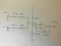
It will work, but you need to place caps over each of the 100K resistors, 10uF or so, more won't harm, for noise reasons. The input cap is a bit on the low side. 2 times gain is 6dB. I would place the input cap in front of the potmeter. Otherwise you can get DC over the potmeter and it will start to crackle. Plus, I would use a non-inverting summing amplifier, because in this set up the (varying) input impedance becomes part of the feedback network.
Last edited:
No, the circuit is correct, although some values could be better chosen.
Since it is intended to operate from a single supply, and the OPamp will attempt to drive the - input to the same voltage as the + input (which is basically the main idea behind any amplifier constructed around an OPamp), the - input must NOT be DC coupled to the pot since one side of the pot is at ground potential, and the + input is referenced to half the power supply. If the pot was DC coupled, it pulls the - input towards ground so the OPamp will have to adjust it's output DC voltage to compensate for this to get the - input back to half the power supply voltage. This will result in a large output DC offset dependant on the potentiometer settings, in fact at pot minimum it may drive the output of the OPamp into positive saturation - and it will produce exactly the problem that moving the coupling caps was intended to 'fix' - DC across the pot. Incidentally, DC across the pot is not as bad (except in producing subsonic 'pumping' when he pot wiper is adjusted), DC current through the wiper is the real problem, this produces noise and micro-arcing which eventually destroys the resistive element along the part where the wiper makes contact with it. In short, the schepatic is correct as it is, the caps athe there to isolate the pot wiper from the half power supply offset present on the - input of the OPamp, which would be passed through to the wiper through the 10k resistors.
Also, do NOT put caps across BOTH 100k resistors that form the half-power supply reference divider. IF the negative side of the power supply is also ground, then it's also the input reference. This means that the 'fake' half power supply 'ground' for the + input of the OPamp must also track this reference for AC, so only the lower 100k resistor must be byopassed with a cap. This also brings me to power supply bypass for the OPamp. If both 100k resistors were bypassed, this would also form a power supply bypass. However, it will also effectively remove any bypass action for the resistors as now anything, including any AC in the power supply (such as ripple, hum, noise) will get divided in half and used as a reference for the OPamp instead of the ground, so the OPamp will now amplify half the ripple just as it will any input signal which is ground referenced (in fact, the amplification factor will be 1 greater than that for the input signal).
The correct way to do power supply decoupling here is to include a small resistor from the actual power supply to the +V power pin of the OPamp. Then, a separate bypass cap is connected from the +V power pin to ground (which is also where the -V power pin of the OPamp is connected). The resistor should be on the order of 10 ohms or so, and the cap is best constructed from a larger electrolytic cap (say 47-220uF) with a smaller foil cap (say 10..100nF) in parallel.
vacuphile's remark about input caps (between pot wipers and 10k resistors) stands, these should be quite a bit biger. s it stands now, the low turnover point for this at max pot setting is 72Hz! 2.2uF would be a better value, although even with those the response is almost 0.5dB down at 20Hz, only due to the input caps (and the 0.22u output cap will add about 1dB to that for a typical 50k load at the output, so the output cap should also be increased in value). The lower turnover frequency does vary depending on the output impedance of whatever is connected to the inputs and also much more depending on the position of the pot wiper (pot values are not specified so difficult to tell within what limits). The gain from each input however does not vary (except due to pot position, however the effective characteristic curve of the pot, i.e. linear, audio taper etc. might be signifficantly affected compared to the raw pot curve, though this is usually not easily audible nor objectionable except if you use truly huge values for the pots, i.e. 1 meg), as the OPamp effectively makes it's - input a virtual ground, looking from the input it's almost a short circuit, so the input resistance viewed from the source is always at least 10k (for a low impedance source and at the extreme positions of the pot) and at most 10k + (1/4 of the pot resistance). This change does affect gain but not as much as the pot, and in the extremes the gain remains defined only by the 10k input and 100k feedback resistors. Between these positions the pot action will dominate so the effective gain from the inputs will always be at most 100k/10k.
The amp does invert (reverses phase). Normally this is not a problem, but there are cases when it may be, such as if the amp is ultimately driving a speaker from a source that is a microphone or may be microphonic (for instance electric guitar). In such cases reversing phase might produce acoustic feedback - but it may also reduce it, as the case may be.
Thankyou very much for the tips, that's really helpfull.
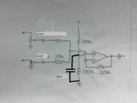
So I'll put a 10uF cap to ground on the lower 100k resistor and increase the input caps to 2.2uF.
It's going to be running off a 12 battery so hum wont be a problem.
I'm thinking of using the LM301 op amp ic.
What is the compensation pin used for?
now to design the board.
So I'll put a 10uF cap to ground on the lower 100k resistor and increase the input caps to 2.2uF.
It's going to be running off a 12 battery so hum wont be a problem.
I'm thinking of using the LM301 op amp ic.
What is the compensation pin used for?
now to design the board.
Attachments
Don't use an LM301 (the compensation pins are for you to add a small capacitor to keep the opamp stable). Its an ancient device with poor performance by todays standards, and it would need careful implementation to get it stable. Don't even think about using one 🙂
Use a something like a TL071 or TL081 which has no worries over stability. Or, the TL061 which is very low power (important for battery use ?)
Because these are FET opamps you could then increase the value of the two 100K's to 1meg and reduce the value of the cap to around 1uf.
Use a something like a TL071 or TL081 which has no worries over stability. Or, the TL061 which is very low power (important for battery use ?)
Because these are FET opamps you could then increase the value of the two 100K's to 1meg and reduce the value of the cap to around 1uf.
Ok, I'll go with a TL071.
You're sure the resistors can be 1 meg?
For the input caps can they be electrolytics or must they be polyester?
Being at half supply voltage they shouldnt ever get reverse biased.
It will be mixing guitar (low output impedance preamp), and a condenser mic.
You're sure the resistors can be 1 meg?
For the input caps can they be electrolytics or must they be polyester?
Being at half supply voltage they shouldnt ever get reverse biased.
It will be mixing guitar (low output impedance preamp), and a condenser mic.
Attachments

Ok, I'll go with a TL071.
You're sure the resistors can be 1 meg?
For the input caps can they be electrolytics or must they be polyester?
Being at half supply voltage they shouldnt ever get reverse biased.
It will be mixing guitar (low output impedance preamp), and a condenser mic.
I would use high quality polypropylene cap for the input.😉
Argh Polyprop?!
$4.30 for a 2.2uf 250V polypropylene Vs $0.22 for a 63V 2.2uF electrolytic at my local store.
Will I hear the difference? This is for an instrunent amp...
$4.30 for a 2.2uf 250V polypropylene Vs $0.22 for a 63V 2.2uF electrolytic at my local store.
Will I hear the difference? This is for an instrunent amp...
Definitely you won't hear any difference.
What worries me a little is that probably active guitar signal will be 10X to 50X what the condenser mic will supply.
What worries me a little is that probably active guitar signal will be 10X to 50X what the condenser mic will supply.
Ok, I'll go with a TL071.
You're sure the resistors can be 1 meg?
For the input caps can they be electrolytics or must they be polyester?
Being at half supply voltage they shouldnt ever get reverse biased.
It will be mixing guitar (low output impedance preamp), and a condenser mic.
1 meg is fine because its a FET opamp and draws no "input current".
Like JMfahey, I wonder whether the input impedance and sensitivities are really suitable, but without knowing specifics its impossible to say.
....
Will I hear the difference? This is for an instrunent amp...
yes
we often think, hey, its only for musical instrument.....
actually, I have lately found that it can be more demanding than music/hifi
my theory is that we have only one node, or a very destinct sound
which makes everything more audible than it would in music/hifi where its mixed with lots of other sounds
and besides, you are affecting a musicians performance with technology
which can be a very delicate process, and easily disturbed
imo..it will be a big mistake to believe it is anything less important than other aspects of music production, or reproduction
Partly agree, but I think that the real point is not electronic, but that the typical guitar speaker has an 8 to 12 dB peak between 2500 and 4000 Hz, drops like a brick beyond that (24dB/oct) and has its own distortion from 5% to 30% or more, due to the fact that the VC is usually the same length as the gap, so even the tiniest movement makes it meet a falling magnetic field= lots of distortion.
In that context, having an Op Amp which reaches 200KHz instead of 20KHz or has 0.01% distortion instead of 0.1% , simply can't be heard.
Of course, higher quality doesn't hurt 😉
Agree that the highest performance possible is needed and justified in Recording equipment, even in PA stuff.
In that context, having an Op Amp which reaches 200KHz instead of 20KHz or has 0.01% distortion instead of 0.1% , simply can't be heard.
Of course, higher quality doesn't hurt 😉
Agree that the highest performance possible is needed and justified in Recording equipment, even in PA stuff.
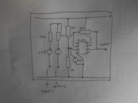
Layout is fine 🙂 If those 2.2uf caps are electros then the + end goes to the opamp. Aslo remember that the opamp output is at half supply voltage so you need a cap on the output too. A 10uf should be fine. Add a 100K from the cap output to ground to define a DC reference so that the cap doesn't charge when not connected to anything.
Add a resistor to the output pin of the 072. 100r may be sufficient.
The 072 does not tolerate parasitic capacitance at all well.
Have a look at Bateman's papers.
A pair of back to back bipolars may give a small improvement. But double the size of series connected caps.
The 072 does not tolerate parasitic capacitance at all well.
Have a look at Bateman's papers.
A pair of back to back bipolars may give a small improvement. But double the size of series connected caps.
Add a 100R on the output?
I've already made the board!
It works awesomely - that is, I cant hear any noise or distortion or anything.
Does what its supposed to do crystal clear.
What is parasitic capacitance? And is the 100ohm supposed to be in series with the output?
This is going to be permanently connected to the next stage/power amp, which is why I didn't have a cap on the output. The next stage has a np cap on the input.
Below is a pic of the board. As you can see, I dont suffer from OCD😀
Attachments
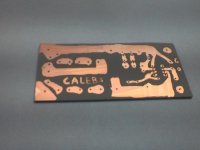
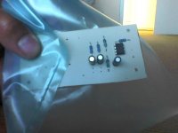
So no cap needed if you already have one on the preamp. Good to see a home made board for once 🙂
(the 100 ohm is just to isolate the opamp output from excessive capacitance such as a long cable run might produce. You should be fine as it is)
(the 100 ohm is just to isolate the opamp output from excessive capacitance such as a long cable run might produce. You should be fine as it is)
This is driving me nuts.
When I tested the circuit on its own, with the output going into a seperate amplifier it was working beautifully but when I installed it in the actual amp then it sounded really distorted and sometimes would go into ghastly oscillations, with the speaker going WhapWhapWhap.
All the voltages seemed normal, and since it was working fine when I ran it with another amp I tried moving the ground around, into star grounding etc, but it didnt help.
I tried putting more smoothing caps at different spots, but no fix.
And it was powered by a battery, so there should be no problems about hum.
Maybe I zapped the IC with ESD? I wasnt wearing my strap.
You won't have zapped the IC by static. Only incorrect voltages and polarity would harm it.
You need to check you have it correctly wired, particularly all the grounds.
Be logical, maybe power the opamp via a battery again and go through it one step at a time.
You need to check you have it correctly wired, particularly all the grounds.
Be logical, maybe power the opamp via a battery again and go through it one step at a time.
- Status
- Not open for further replies.
- Home
- Amplifiers
- Solid State
- Is this preamp circuit OK?