There is a large difference between soft start and delay. Soft start simply prevents excessive inrush current, reducing stress on rectifiers, caps and active components in the pre-amp or amplifier, and should reduce the likelihood of nuisance fuse blowing.
You need the delay or better still a mute on the pre-amplifier output that prevents the pre-amp from unmuting until dc conditions are stable and the output coupling caps have fully charged. (A simple time delay mute will work fine here.)
While your pre-amplifier is warming up the output coupling capacitors are also charging, while this charging is occurring a voltage develops across the output resistors and anything that the pre-amplifier is connected to. This can lead to a damaged power amplifier input stage if the voltage is large enough, and if the amplifier unmutes while this is still happening large currents can flow through your speaker voice coils. At the least you will get a pretty big pop. (Speaker relay contact damage is also possible over time.)
A varistor as I have advocated before only reduces the magnitude of the inrush current over a very limited period of time. It will be done long before the pre-amp has warmed up. Both delay and inrush suppression are appropriate here for use with a solid state amplifier.
You can increase the value of C in your 555 based unmute delay circuit or increase R. You may need to find a low leakage electrolytic for this application if you choose a much larger cap than what you are using now. A time constant of a minute or so should suffice. This will be most effective if the relay is arranged to short the outputs to ground rather than opening them. This provides the lowest tc charging path during warm up, and when unmuted the contacts are not in the signal path. Don't use a solid state relay (SSR ) in the signal path. Reed relays should also be avoided as in this application they are likely to weld contacts.
Edit: extra details
You need the delay or better still a mute on the pre-amplifier output that prevents the pre-amp from unmuting until dc conditions are stable and the output coupling caps have fully charged. (A simple time delay mute will work fine here.)
While your pre-amplifier is warming up the output coupling capacitors are also charging, while this charging is occurring a voltage develops across the output resistors and anything that the pre-amplifier is connected to. This can lead to a damaged power amplifier input stage if the voltage is large enough, and if the amplifier unmutes while this is still happening large currents can flow through your speaker voice coils. At the least you will get a pretty big pop. (Speaker relay contact damage is also possible over time.)
A varistor as I have advocated before only reduces the magnitude of the inrush current over a very limited period of time. It will be done long before the pre-amp has warmed up. Both delay and inrush suppression are appropriate here for use with a solid state amplifier.
You can increase the value of C in your 555 based unmute delay circuit or increase R. You may need to find a low leakage electrolytic for this application if you choose a much larger cap than what you are using now. A time constant of a minute or so should suffice. This will be most effective if the relay is arranged to short the outputs to ground rather than opening them. This provides the lowest tc charging path during warm up, and when unmuted the contacts are not in the signal path.
Don't use a solid state relay (SSR ) in the signal path. Reed relays should also be avoided as in this application they are likely to weld contacts.Edit: extra details
Thanks Kevin,
I have now tried adding a 10 uF to the 47 uF in the delay circuit and it slightly increases the delay period. I'll look around for one of those low leakage caps. When I added another 47 uF, the relay did not switch in!
In my case, it appears that from a cold start, I need a delay of at least 40 seconds for things to 'settle down'. A minute would probably ber a good idea!
And I will look at a soft-start too! 🙂
Nuuk said:Thanks Kevin,
I have now tried adding a 10 uF to the 47 uF in the delay circuit and it slightly increases the delay period. I'll look around for one of those low leakage caps. When I added another 47 uF, the relay did not switch in!
In my case, it appears that from a cold start, I need a delay of at least 40 seconds for things to 'settle down'. A minute would probably ber a good idea!
And I will look at a soft-start too! 🙂
Try adding a fixed resistor the same value of ohms as the trimmer (within 20%, not critical) to the existing trimmer, in series. That should get you the delay you want.
I have 500K trimmers on my delay circuit. The nearest resistor value I had to those was 330K but that still didn't give me a long enough delay. So I inserted 1M in series with the trimmer and can now easily reach the one minute delay target (with the 47 uF cap).
I'm still not sure if those 100n caps need to be fitted to both pin connections of the heater supply. I'm using one valve per channel with the heaters wired in series.
I'm still not sure if those 100n caps need to be fitted to both pin connections of the heater supply. I'm using one valve per channel with the heaters wired in series.
Nuuk said:I have 500K trimmers on my delay circuit. The nearest resistor value I had to those was 330K but that still didn't give me a long enough delay. So I inserted 1M in series with the trimmer and can now easily reach the one minute delay target (with the 47 uF cap).
I'm still not sure if those 100n caps need to be fitted to both pin connections of the heater supply. I'm using one valve per channel with the heaters wired in series.
What kind of relays did you use? a link would be nice 🙂 thanks
Nuuk said:
looking at the info from the farnell site, the max contact voltage is 150V?
This circuit is used on the output of a pre-amplifier, after the coupling capacitors (in a tube pre) and a 150V rating is more than adequate, usually the dc present during warm up should be on the order of a couple of volts or less.
I have used a very similar circuit for years based on a 7555 cmos timer and small low leakage tantalum timing cap.
I have used a very similar circuit for years based on a 7555 cmos timer and small low leakage tantalum timing cap.
kevinkr said:This circuit is used on the output of a pre-amplifier, after the coupling capacitors (in a tube pre) and a 150V rating is more than adequate, usually the dc present during warm up should be on the order of a couple of volts or less.
I have used a very similar circuit for years based on a 7555 cmos timer and small low leakage tantalum timing cap.
I thought the 150V rating relates to AC. and I thought that it's 240VAC in the UK (the thread starter's location)
thanks for the clarification 🙂
I thought the 150V rating relates to AC. and I thought that it's 240VAC in the UK (the thread starter's location)
The relay is not switching the mains supply!
Before it is activated, its closed contacts short the output signal of the preamp to ground. So any unwanted voltages are also shunted to ground instead of going to the power amp input.
When the delay circuit activates the relay, the contacts are opened and the signal is no longer shorted to ground.
At worst, there should only ever be a few volts while the valves are warming up so that relay is more than adequate. 😉
SY said:
Yes!
you mentioned I need to connect the capacitor from heater pin to AC ground.
I'm wondering why not b+ ground.
thank you.
Hi Nuuk, At the transcendent forum (grounded grid forum) CB posted a power up time delay relay that shorts the signal to ground as well, very similar to yours in that the signal is shorted during power up and then the relay (un-shorts) the signal after the delay. It was recommended to increase the cap to a 220uF for an extra 4-5 second delay.
I built this circuit w/ Eagle but have not etched the boards yet to check how it works I would be happy to post the Eagle files if anyone is interested.
Power-On Time Delay Relay
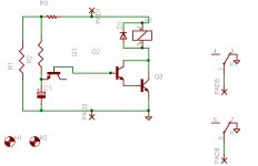
Here's a power-on time delay relay circuit that takes advantage of the emitter/base breakdown voltage of an ordinary bi-polar transistor. The reverse connected emitter/base junction of a 2N3904 transistor is used as an 8 volt zener diode which creates a higher turn-on voltage for the Darlington connected transistor pair. Most any bi-polar transistor may be used, but the zener voltage will vary from about 6 to 9 volts depending on the particular transistor used. Time delay is roughly 7 seconds using a 47K resistor and 100uF capacitor and can be reduced by reducing the R or C values. Longer delays can be obtained with a larger capacitor; the timing resistor probably shouldn't be increased past 47K. The circuit should work with most any 12 volt DC relay that has a coil resistance of 75 ohms or more. The 10K resistor connected across the supply provides a discharge path for the capacitor when power is turned off and is not needed if the power supply already has a bleeder resistor.
I built this circuit w/ Eagle but have not etched the boards yet to check how it works I would be happy to post the Eagle files if anyone is interested.
Power-On Time Delay Relay
Here's a power-on time delay relay circuit that takes advantage of the emitter/base breakdown voltage of an ordinary bi-polar transistor. The reverse connected emitter/base junction of a 2N3904 transistor is used as an 8 volt zener diode which creates a higher turn-on voltage for the Darlington connected transistor pair. Most any bi-polar transistor may be used, but the zener voltage will vary from about 6 to 9 volts depending on the particular transistor used. Time delay is roughly 7 seconds using a 47K resistor and 100uF capacitor and can be reduced by reducing the R or C values. Longer delays can be obtained with a larger capacitor; the timing resistor probably shouldn't be increased past 47K. The circuit should work with most any 12 volt DC relay that has a coil resistance of 75 ohms or more. The 10K resistor connected across the supply provides a discharge path for the capacitor when power is turned off and is not needed if the power supply already has a bleeder resistor.
Attachments
That's an interesting circuit and useful alternative to the 555 circuit. I am thinking along the lines that it is worth putting one of these delay circuits in any buffer/preamp to avoid any 'nasties' at power up. So it's actually one PCB I would be interested in! 😉
The big resistor R3 is a voltage dropper, the circuit was designed for 12V, and I’ll be running mine from a 15V supply it could probably be dropped down to a 2 watt. The relay is an
http://rocky.digikey.com/WebLib/Omron Web Data/G6K.pdf
The board measures 1.5 X 2.25”
Like I mentioned I haven't etched the boards yet so please double check and let me know if you spot something.
http://rocky.digikey.com/WebLib/Omron Web Data/G6K.pdf
The board measures 1.5 X 2.25”
Like I mentioned I haven't etched the boards yet so please double check and let me know if you spot something.
Attachments

I'm having trouble uploading the .brd file, I'll upload later after I talk to the smarter half of my brain, my wife...
- Status
- Not open for further replies.
- Home
- Amplifiers
- Tubes / Valves
- Is this heater supply OK?