The simplest and most reliable way to drop 40V at 40mA is a 5 Watt 1k Ohm resistor. Bypass the new B+ voltage point with a 50uF capacitor that has a high enough voltage rating.
40V and 35mA, 1140 Ohms, etc.
Just adjust the final resistance value to get the exact new B+ voltage you want.
40V and 35mA, 1140 Ohms, etc.
Just adjust the final resistance value to get the exact new B+ voltage you want.
Propably 1 or 2 zener diodes alone would do, but depends on the PS.
But why would you want to use a fixed voltage drop (zener) before your first PS cap, instead of dropping that voltage in the resistor of CRC smoothing?
Have you thougth about that?
But why would you want to use a fixed voltage drop (zener) before your first PS cap, instead of dropping that voltage in the resistor of CRC smoothing?
Have you thougth about that?
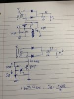
Reverse the zeners and exchange pnp to npn, npn collector has to be at ground, pnp collector conn to CT
Swingarm63,
Do you want a regulated B+ voltage?
Most all of what has been proposed in this thread will work, but . . .
It merely drops about 40V off of the Un-regulated B+.
That means, the new B+ is also Un-regulated.
If Un-regulated is all that is wanted, a simple series resistor, and capacitor to ground from the reduced B+ voltage is all that is needed.
The proposals in this thread are more complex, but all that complexity does not even regulate the final B+ voltage.
Just saying

I often use a "small" capacitor as the first capacitor after the rectification diodes. Maybe 1 to 2 uF? Then comes a resistor or a choke, and more capacitors. This will reduce the voltage....
The double emitter arrows; is that intended to display a Darlington?It seems that the tip147 should be a pnp ? Is this the wrong component ?
Is it a tip142 instead?
Thanks
View attachment 1275351
- Home
- Amplifiers
- Tubes / Valves
- Is this drawing correct?