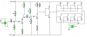
hi i am a bit of a newbie when it comes to designing amplifers and i would like to know if this design (atached) will work. i am sure there are many mistakes in the design and i would very much apreciate if they could be pointed out.
bare in mind this amp is for a sub and therefore does not need to be high quality or have low distortion. it just needs to be loud.
i have simulated this design and it works. but that is just with a cheap computer program.
oh and what is the maximum voltage that a line in will be?
thanx
bare in mind this amp is for a sub and therefore does not need to be high quality or have low distortion. it just needs to be loud.
i have simulated this design and it works. but that is just with a cheap computer program.
oh and what is the maximum voltage that a line in will be?
thanx
Attachments
No, your DC offset will drift all over the map with temperature and supply voltage drift. There are more problems but ....
There are lots of simple, basic amps to copy from. Why not?
There are lots of simple, basic amps to copy from. Why not?
I haven't bothered grinding any numbers, but just looking at it the zero crossing distortion in the output is going to be huge. And with no negative feedback to help, it probably wouldn't even sound right driving a sub-woofer. Try looking around at some other output stage designs for some biasing ideas.
anatech said:No, your DC offset will drift all over the map with temperature and supply voltage drift. There are more problems but ....
There are lots of simple, basic amps to copy from. Why not?
Yes this is quite a problem. If you direct couple the speaker to the outputs, then you need some type of feedback loop, or really precise transistors and very accurate biasing


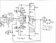
If high freq. responce is not required, and stable DC offset IS required, then try using an OP- Amp as a differential, but be sure that it has a very high open loop gain, and no internal neg. feedback loop. Like the good ol' 741 for cheapness.
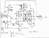
Take this circuit topology for an example, and feel free to modify it.😎
Attachments

Commentable Thoughts
hi ,
This amp is only good for simulation purposes . Not in reality due to temperature instability leads to thermal runaway , no feedback.
Regards
AmPmAn
hi ,
This amp is only good for simulation purposes . Not in reality due to temperature instability leads to thermal runaway , no feedback.
Regards
AmPmAn
i designed a circuit because i want to understand how it works. simply copying a circuit is pointless as this will give little understanding of how it works.
thanks for all the replies, i am going to modify one of the desigins that have been posted and see where i go from there.
thanks for all the replies, i am going to modify one of the desigins that have been posted and see where i go from there.
hughmon said:I haven't bothered grinding any numbers, but just looking at it the zero crossing distortion in the output is going to be huge.
How many of us have tried to listen to an amp with zero bias in the output stage with real music and how many of us can tell the difference between zero bias and optimal bias?
I had a hard time telling them apart, especially during casual listening sessions and without knowing the level of biasing.
Crossover distortion
Hi millwood,
Boy, I can hear it. Maybe because I was a service tech for years and I naturally listen for it. There are lots of amps I can't listen to.
In this application you may still hear it if the woofer is forward firing and there is no acoustic filtering.
-Chris
Hi millwood,
Boy, I can hear it. Maybe because I was a service tech for years and I naturally listen for it. There are lots of amps I can't listen to.
In this application you may still hear it if the woofer is forward firing and there is no acoustic filtering.
-Chris
- Status
- Not open for further replies.
- Home
- Amplifiers
- Solid State
- is this design sound?