@OmeEd
Thank you taking time to answer my questions here. I am trying to use +/- 32 VDC here because intent to use 4x12VAC secondary output transformer. 12VAC can be used for DC Protection circuit in another PCB. Normally for 20W Class-A, 2x20VAC transformer is good enough to get +/-25VDC.
Since the NE5532A can have close to +/-19V voltage swing, maybe it is good to have 20W Class-A output. That's why I am asking for help to adjust this circuit, even I am sure this is not a excellent one schematic to have 20W Class-A, but it might work to have low distortion with "Class-A music taste". 🙂
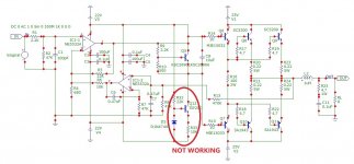


the zener of 10V will limit your excursion of negative voltages too much, you may replace it by two regular diodes or other type of constant current source with low voltage drop
The current source will have slightly less voltage swing than the resistors.
I suggest not trying to push the NE5532. The voltage (22V), current (10mA), and dissipation (600mW) are all too high.
There are plenty of discrete transistor amplifiers on this site.
Ed
I suggest not trying to push the NE5532. The voltage (22V), current (10mA), and dissipation (600mW) are all too high.
There are plenty of discrete transistor amplifiers on this site.
Ed
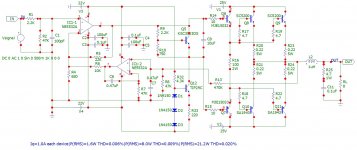
In my opinion the double output stage is not necessary, just use large heat sinks. Saves some costs.
Thank you @EdGr very much for sound suggestion. Indeed I agree that the workload of NE5532A is too much. I may simulate with +/- 20VDC for NE5532A.The current source will have slightly less voltage swing than the resistors.
I suggest not trying to push the NE5532. The voltage (22V), current (10mA), and dissipation (600mW) are all too high.
There are plenty of discrete transistor amplifiers on this site.
Ed
That's a good ideal because only 20W output is wanted. Under normal listening level (SPL 97dB), 20W (13dBw) can use as low as 84dB sensitivity speakers.In my opinion the double output stage is not necessary, just use large heat sinks. Saves some costs.
Many thanks @anibal @EdGr for all excellent advice and suggestions, I learn a lot for this simulations.
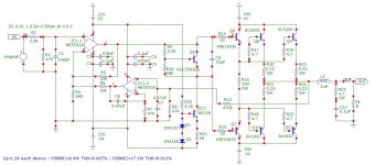
Following resulting to about 20W Class-A output. 6mA constant current used for NE5532A, maybe that's good enough to force NE5532A working at class-a condition. (I am not 100% sure for this, will search.) The quiescent current at each output transistor is about 1.0Amp.
Following resulting to about 20W Class-A output. 6mA constant current used for NE5532A, maybe that's good enough to force NE5532A working at class-a condition. (I am not 100% sure for this, will search.) The quiescent current at each output transistor is about 1.0Amp.
Attachments
With current condition for the NE5532A, 44V x 6mA = 264 mW, according to specification, the "Junction-to-ambient thermal resistance" (85degreeC/W), the chip temperature would be increased by 23 degree C. It seems ok to be safe.
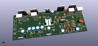
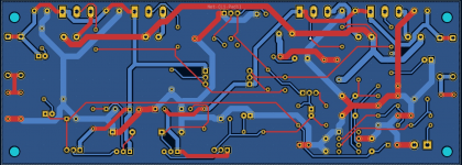
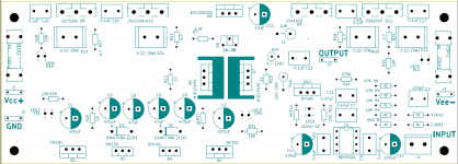
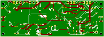
To complete the learning process, PCB file has been made in KiCAD 6.0, for fun only. Maybe someday I will make PCB to tryout. Not sure yet.
Attachments
- Home
- Amplifiers
- Solid State
- Is This Class-A BJT Amplifier Schematic Worth A Tryout?