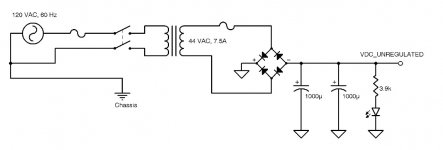
Posting the schematics to make the thread self-contained.
MOSFET or transistor options.
MOSFET or transistor options.
Attachments
Last edited:
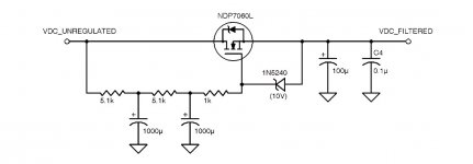
you better go with lm 317 slow turn on schematic.Also, if anyone knows, would a capacitor multiplier like this also give a slow(er) ramp up of the voltage? Smoothing out the turn on surge for say cold filaments. If so Which capacitor would determine the rise time?
Attachments

You can design in any time constant you wish, 330k + 100uf give you 33 seconds.It takes many seconds to heat a tube filament. A capacitor multiplier works with (lots) of milliseconds, nevertheless it will probably never reach the 20 to 30 seconds for an average tube to start conducting.
Regards, Gerrit
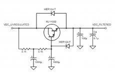
The schematic of the DAC 4 is not really a cap multiplier as it adds a zener to the base of the pass transistor. It's acting more like a poor regulator.
I'm puzzled though by the crazy quintuple emitter follower they use. Anyone has an idea on why they would want to do that ?
I have to assume it's to get the highest hFe value they can, possibly because their zener based "regulator" really doesn't handle varying loads well. I probably would have used a FET before I used a quintuple EF.
Caution should be used before trying to do delayed start up with a circuit like this as you may run into SOA limitations of your pass transistor, especially if you power cycle the device (so the filament would still be hot).