I found a project article that promises to reduce ripple greatly at a fraction of the heat dissipation of a regulator. The author sets this up for low voltage supply. I have a few questions... Is this a regulator or some type of capacitor multiplier, or neither? Also what mosfet would I use if I wanted to scale this circuit up to handle B+ level voltages? It looks promising to me as a preamp DC filament supply as it wouldn't dissipate as much as a regulator and regulating filaments isn't really critical anyway. For B+ it looks like a simpler alternative to full out regulation, a middle ground between unregulated and regulated?
An Alternative to Linear Regulators: Equivalent Power-Line Ripple Rejection with Less Power Dissipation | audioXpress
Thanks
An Alternative to Linear Regulators: Equivalent Power-Line Ripple Rejection with Less Power Dissipation | audioXpress
Thanks
yes, it is a capacitor multiplier.you find a bjt similar one in the art of electronics.you have a more advanced one in DAC4
Attachments
Last edited:
So the low dissipation key here is the use of a "logic level" mosfet? Looking at the list of available logic level mosfets, B+ voltages are out of the question. But maybe this logic level mosfet can be used to control a higher voltage mosfet as the actual pass device? This is beyond my skill level, just wondering. Capacitor multipliers seem like a nice middle ground if they dissipate so much less.
yes, it is a capacitor multiplier.you find a bjt similar one in the art of electronics.you have a more advanced one in DAC4
Thanks, I just ordered a used copy of the art of electronics.
Also, what is DAC4? Is that another book I should own?
hopefully you ordered the third edition...i have no idea if you can find it in the other 2 editions.
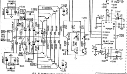
AUDIO-NOTE DAC4 SCH Service Manual download, schematics, eeprom, repair info for electronics experts
AUDIO-NOTE DAC4 SCH Service Manual download, schematics, eeprom, repair info for electronics experts
Last edited:
So the low dissipation key here is the use of a "logic level" mosfet? Looking at the list of available logic level mosfets, B+ voltages are out of the question.
What's the voltage across the device? If you have 500V of B+ but 3V across the fet, the fet doesn't care.
Of course if there's some kind of nasty short on the output side, well, that's a whole different thing!
What's the voltage across the device? If you have 500V of B+ but 3V across the fet, the fet doesn't care.
Thanks, that sounds like a plan. I'll have to get a few of these NDP7060's on my next Mouser order and try it at 30 volts, then see if I can up the voltage to B+, measuring along the way. I'm still a little confused about where the breakdown voltages are at I guess, I need to experiment. Nothing for me seems to sink in until I do an experiment.
If this little circuit module doesn't much care about the input voltage, I can see myself wanting to use it making vintage unregulated circuits quieter without much effort. Just drop in a little board after the power supply.
Another way to look at it is to presume you have a certain B+ voltage and a certain amount of current draw, then start filling in numbers.
Dissipation is the on resistance of the mosfet and current its passing. Not uncommon today to find mosfets with Rds values equal to the pcb traces.
"Lower dissipation" is relative and misleading.
Regulators "dissipate more" only because they keep output voltage constant, and are typically fed from a significantly higher voltage unregulated supply, dissipation is current times voltage drop.
Poorly called "capacitance multipliers" (which they are NOT), are poor regulators, dissipation is STILL voltage drop times current , only since they do not even attempt to regulate output voltage, just absorb ripple, typically voltage drop is lower.
I always found that label misleading.
I share the same opinion. This circuit does not multiply the reservoir capacitance but uses a transistor to suppress the ripple. It is better called active ripple suppressor.JMFahey said:Poorly called "capacitance multipliers" (which they are NOT), are poor regulators, dissipation is STILL voltage drop times current , only since they do not even attempt to regulate output voltage, just absorb ripple, typically voltage drop is lower.
I always found that label misleading.
"Lower dissipation" is relative and misleading.
Regulators "dissipate more" only because they keep output voltage constant, and are typically fed from a significantly higher voltage unregulated supply, dissipation is current times voltage drop.
Poorly called "capacitance multipliers" (which they are NOT), are poor regulators, dissipation is STILL voltage drop times current , only since they do not even attempt to regulate output voltage, just absorb ripple, typically voltage drop is lower.
I always found that label misleading.
This explains it well, thanks. The work of a regulator having to trim out the voltage above its drop out point causes heat, as well as the load. In cases where one doesnt need regulation, but goes ahead and does it anyway, just to get the fine ripple performance is what I'm thinking. This is simpler and cheaper if you dont need the whole regulator, you just get the active ripple removal?
I share the same opinion. This circuit does not multiply the reservoir capacitance but uses a transistor to suppress the ripple. It is better called active ripple suppressor.
Yeah there seems to be some hyperbole in the term "capacitor multiplier" that seems to have stuck!
You better wait for your copy of The AoE as it is explained much better in about 5 places what it does.People often try to diminish the value of simple concepts that work great. Analyzing the DAC-4 multiplier you'll see that it has all the ingredients you need .Some ferite beads might have been usefull to there, but it's complex enough...
You better wait for your copy of The AoE as it is explained much better in about 5 places what it does...
I've experimented with unregulated and regulated already, loaded them at different levels to see how they behave, changed supply voltage, ran out the transformers capacity to see what happens, etc. I do this sometimes with 6 meters attached! when I stumbled on this circuit I have to now do the same. They say cap multipliers work best with a known constant load. To me that screams an unregulated DC filament supply application. Maybe maida for B+ and simple cap multiplier for filaments. Or In class A maybe all cap multipliers since the load won't swing much?
Last edited:
Analyzing the DAC-4 multiplier you'll see that it has all the ingredients you need .Some ferite beads might have been usefull to there, but it's complex enough...
The schematic of the DAC 4 is not really a cap multiplier as it adds a zener to the base of the pass transistor. It's acting more like a poor regulator.
I'm puzzled though by the crazy quintuple emitter follower they use. Anyone has an idea on why they would want to do that ?
The issue with a regulator is that you have to plan on line voltage variations. So your input must remain a certain amount above your output even with worst case line voltage sags. This results in significant dissipation when line voltage is nominal or high.
With a circuit where output tracks a percentage of input, you can design for an output voltage that is closer to the input voltage without worrying much about input voltage variations.
I'm thinking of building a ripple rejection circuit for a 40W SE tube amp. Since the voltages and currents will be high, the idea of making the power supply output fully regulated is unattractive. I'd need a pretty large heatsink. With an output that varies with input, I should be able to keep dissipation in the pass device well under 10W per channel.
Also, if anyone knows, would a capacitor multiplier like this also give a slow(er) ramp up of the voltage? Smoothing out the turn on surge for say cold filaments. If so Which capacitor would determine the rise time?
It takes many seconds to heat a tube filament. A capacitor multiplier works with (lots) of milliseconds, nevertheless it will probably never reach the 20 to 30 seconds for an average tube to start conducting.
Regards, Gerrit
Regards, Gerrit
- Home
- Amplifiers
- Tubes / Valves
- Is this circuit a capacitor multiplier a regulator or neither?