Hi there
My transformer secondary is 2x18vac
My application need 30-40vdc 1-1.5a
Hence to lower the b+ I want to apply choke immediately after rectifier
The choke spec is
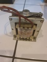
5mh and 0.3ohm. No idea the current rating. But from the wire is more than enough. At least 1.5mm
Can i use these chokes as input choke which followed by 82mf -1ohm resistor-82mf ?
I attach the picture of the choke compare with to-3
Thanks in advance
Regards
Erwin
My transformer secondary is 2x18vac
My application need 30-40vdc 1-1.5a
Hence to lower the b+ I want to apply choke immediately after rectifier
The choke spec is
5mh and 0.3ohm. No idea the current rating. But from the wire is more than enough. At least 1.5mm
Can i use these chokes as input choke which followed by 82mf -1ohm resistor-82mf ?
I attach the picture of the choke compare with to-3
Thanks in advance
Regards
Erwin
Attachments
Last edited:
Erwin, how did you determine the choke's inductance and dc resistance ?
The choke inductance is likely about 10 times too small to allow 'choke input' style reduction of DC output voltage (ie. to constrain output to circa 30Vdc from a 36Vac winding, rather than circa >40Vdc from a capacitor input style filter).
I suggest you use PSUD2 simulation to indicate what choke inductance would suit your application. You can post a screen-shot of your simulation if you are unsure about setting it up. Note that the measurement of your power transformer (secondary winding open-circuit voltage, and DCR, and primary winding DCR and voltage), along with choice of rectifier, and confirmation of choke parameters, are going to be key to getting a good estimate of what can be achieved.
I determined the choke inductance and dcr using LCR meter
Its a 300va transformer
with primary dcr 3.3ohm
secondary 36v tap is 0.4ohm
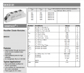
rectifier is semikron skkd 81/14
https://www.semikron-shop.com/out/media/ds/SEMIKRON_DataSheet_SKKD_81_07897092.pdf
in psud, I just realized can setup the new rectifier
<?xml version="1.0" encoding="UTF-8"?>
<rectifier>
<name>skkd8114</name>
<description>1N4001 imported from PSUD2</description>
<version>211</version>
<creationdate>2019-11-23 17:30:32</creationdate>
<type>SS</type>
<vlaw>20</vlaw>
<vfac>9.353</vfac>
<dres>0.042</dres>
<vpiv>50</vpiv>
<ipks>30</ipks>
<ipkr>6</ipkr>
</rectifier>
help me fill in the parameter please. i attached the screenshot.
i tried the hagerman calculator
http://www.hagtech.com/theory.html

thanks in advance for all the help and inputs
Its a 300va transformer
with primary dcr 3.3ohm
secondary 36v tap is 0.4ohm
rectifier is semikron skkd 81/14
https://www.semikron-shop.com/out/media/ds/SEMIKRON_DataSheet_SKKD_81_07897092.pdf
in psud, I just realized can setup the new rectifier
<?xml version="1.0" encoding="UTF-8"?>
<rectifier>
<name>skkd8114</name>
<description>1N4001 imported from PSUD2</description>
<version>211</version>
<creationdate>2019-11-23 17:30:32</creationdate>
<type>SS</type>
<vlaw>20</vlaw>
<vfac>9.353</vfac>
<dres>0.042</dres>
<vpiv>50</vpiv>
<ipks>30</ipks>
<ipkr>6</ipkr>
</rectifier>
help me fill in the parameter please. i attached the screenshot.
i tried the hagerman calculator
http://www.hagtech.com/theory.html
thanks in advance for all the help and inputs
Attachments
if this choke input not feasible..
any suggestion on how to drop few volt without much heat?
how bout resistor input? 1ohm for 1a current draw? whats the rating of this 1ohm resistor? p=I*I*R=1watt. whats the rating if use as an input resistor after rectrifier. i simulate in psud it drop more voltage than 1ohm after capacitor
thanks
any suggestion on how to drop few volt without much heat?
how bout resistor input? 1ohm for 1a current draw? whats the rating of this 1ohm resistor? p=I*I*R=1watt. whats the rating if use as an input resistor after rectrifier. i simulate in psud it drop more voltage than 1ohm after capacitor
thanks
A choke will still heat up.
A different transformer would be better, otherwise use a chassis mounted power resistor on a heatsink.
A different transformer would be better, otherwise use a chassis mounted power resistor on a heatsink.
PSUD2 indicates you may stay under 40V at 1A, which sounds like your aim, but getting a better estimate needs better detail including mains AC voltage.
Aspects to note are that your mains voltage could vary (eg. go up by 5%, and hence 40V could get to 42V). Your choke inductance could have a noticeably different value than the LCR measures, as the LCR likely applies less than 1V across the choke, but the choke experiences a lot more in your circuit, plus it has to handle significant level of DC current.
Your semipak is an industrial level diode and way beyond what is needed. PSUD2 indicates the diode peak current is quite low (due to the choke), so you could use something like a 3 to 6A rated diode. You also need a diode bridge (4 diodes), so a 6A bridge would be quite common.
But that is all detail, and I'd recommend you make up the circuit with the parts you have and measure what you get with your load range - unless there is some unforetold hassle with doing that? If you were a volt or so higher than you wanted, and had the semipak at hand, then connect the 2 diodes in series with your load.
Thanks for the replyPSUD2 indicates you may stay under 40V at 1A, which sounds like your aim, but getting a better estimate needs better detail including mains AC voltage.
Aspects to note are that your mains voltage could vary (eg. go up by 5%, and hence 40V could get to 42V). Your choke inductance could have a noticeably different value than the LCR measures, as the LCR likely applies less than 1V across the choke, but the choke experiences a lot more in your circuit, plus it has to handle significant level of DC current.
Your semipak is an industrial level diode and way beyond what is needed. PSUD2 indicates the diode peak current is quite low (due to the choke), so you could use something like a 3 to 6A rated diode. You also need a diode bridge (4 diodes), so a 6A bridge would be quite common.
But that is all detail, and I'd recommend you make up the circuit with the parts you have and measure what you get with your load range - unless there is some unforetold hassle with doing that? If you were a volt or so higher than you wanted, and had the semipak at hand, then connect the 2 diodes in series with your load.
so you recon that the choke might be higher or lower inductance in actual application compare to the measured by LCR meter?
My main is 220v 50hz. it will swing down. and never above 220
i am building sit Lamp which could take up to 50vdc but i would like to keep it lower as i am afraid that my heatsink wont be able to handle the heat
Are the 18V windings completely separate, or are they connected via a center-tap? This could change the outcome completely
In this case, I would direct you to the 3/2 multiplier in:
https://www.diyaudio.com/community/...here-is-the-legacy-thread.387391/post-7051987 this thread
Parallel the 18V windings, and connect them to the 3/2 multipiler: the result will be 1.5*1.4*18=37.8V, in fact somewhat lower under load, thus around 35V, probably what you are looking fr
https://www.diyaudio.com/community/...here-is-the-legacy-thread.387391/post-7051987 this thread
Parallel the 18V windings, and connect them to the 3/2 multipiler: the result will be 1.5*1.4*18=37.8V, in fact somewhat lower under load, thus around 35V, probably what you are looking fr
You could also use a LM317HV 1.5amp 60v adjustable voltage regulator and this would also reduce ripple without needing large capacitors.
It is an option, but it demands more rms current from the transformer, and requires more dissipation in the ballast.
Using a base DC voltage closer to the target voltage reduces the losses, and does not require unordinary components, meaning it is probably the way go for sensible people (but others may disagree; I have no problem with that)
Using a base DC voltage closer to the target voltage reduces the losses, and does not require unordinary components, meaning it is probably the way go for sensible people (but others may disagree; I have no problem with that)
Hello,Erwin, how did you determine the choke's inductance and dc resistance ?
The choke inductance is likely about 10 times too small to allow 'choke input' style reduction of DC output voltage (ie. to constrain output to circa 30Vdc from a 36Vac winding, rather than circa >40Vdc from a capacitor input style filter).
I suggest you use PSUD2 simulation to indicate what choke inductance would suit your application. You can post a screen-shot of your simulation if you are unsure about setting it up. Note that the measurement of your power transformer (secondary winding open-circuit voltage, and DCR, and primary winding DCR and voltage), along with choice of rectifier, and confirmation of choke parameters, are going to be key to getting a good estimate of what can be achieved.
Erwin asked me in a personal message about this and VERY probably the quoted information is right you will need more than a few mH to make it work as a true choke input. If the pictured choke is an AC type it wont like to be used as a choke input with 1A dc current all the time.
Erwin does have the LL2733 ( lundahl) for another application. I told him to try these, these are the ones made to be used like this.
greetings, eduard
Thanks alot for all the inputs
I
Thanks you so much for sharing with the community. Really appreaciate that.
I would try to understand it. Its good to know we have that option. I will give a good read on the posts.
Thx
I
Excellent.In this case, I would direct you to the 3/2 multiplier in:
https://www.diyaudio.com/community/...here-is-the-legacy-thread.387391/post-7051987 this thread
Parallel the 18V windings, and connect them to the 3/2 multipiler: the result will be 1.5*1.4*18=37.8V, in fact somewhat lower under load, thus around 35V, probably what you are looking fr
Thanks you so much for sharing with the community. Really appreaciate that.
I would try to understand it. Its good to know we have that option. I will give a good read on the posts.
Thx
Hi EduardHello,
Erwin asked me in a personal message about this and VERY probably the quoted information is right you will need more than a few mH to make it work as a true choke input. If the pictured choke is an AC type it wont like to be used as a choke input with 1A dc current all the time.
Erwin does have the LL2733 ( lundahl) for another application. I told him to try these, these are the ones made to be used like this.
greetings, eduard
Really appreciate on the helps.
I did experience the sweatness of the chokes to the music presentation and i love it. Hence the pm
- Home
- Amplifiers
- Power Supplies
- Is this choke can be use as input choke after rectifier?