I think it would be worth exploring. I don't see where
it is patented, and I would be surprised if it was.
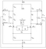
I think, though, you will want to alter R11 and R12 to
200 ohm (or so) potentiometers, as you can't assume
that the MOSFETs Vgs figures will be the same as the
ones used by the designer, the result being a bias
figure which might be catastrophically different.
Start with R11 and 12 at minimum resistance and bias it
up to taste.....
it is patented, and I would be surprised if it was.
I think, though, you will want to alter R11 and R12 to
200 ohm (or so) potentiometers, as you can't assume
that the MOSFETs Vgs figures will be the same as the
ones used by the designer, the result being a bias
figure which might be catastrophically different.
Start with R11 and 12 at minimum resistance and bias it
up to taste.....
Nelson,
I believe this might be a good topology for a Balanced pre-amp.
How about replacing R11, R15 and R12, R16 with a Vgs multiplier and R13 and R14 with current sources?
Jam
I believe this might be a good topology for a Balanced pre-amp.
How about replacing R11, R15 and R12, R16 with a Vgs multiplier and R13 and R14 with current sources?
Jam
Like, I'm surprised that Jam wants current sources?
Actually, in this case I happen to agree with him. Whether as an amp or a preamp, I'd think current sources would be a decent possibility.
The values for R5 & R6 look a bit scant to me. I'd go for 10k as an absolute bare minimum so as not to load down the preceding stage or source.
Jam,
You're wanting push-pull outputs on a preamp?
Grey
I remember form the BOSOZ article that the voltage gain stage has poor distortion figures say above 10V output.
By how much could that be improved with CS, and going to even higher PS voltages?
I wish I had the equipment to do the distortion experiment.
By how much could that be improved with CS, and going to even higher PS voltages?
I wish I had the equipment to do the distortion experiment.
Thanks for the reply guys!
I'll consider all comments
Dear Pass: funny you say that about the patent.. this design is also based on patent 5,376,899 but with the stuff left out that I don't understand 🙂
My only wish is some way of including the power stage into a feddback loop...this should improve liearity above class A bias point in 8 ohm loads..
I realy wanted a headphone amp and I hope the whole thing works
Thanks again..
greetings,
thijs
Grey,
The comp. output stage would work if it was biased high enough. Just in case you think I that I have lost it, my choice of output stage would be a single ended, current sourced (had to get this in somewhere) mosfet.
Cascodeing the comp.(push-pull) output stage might be a worthwhile experiment though (pre-amp only).
Jam
Thijs,
A headphone amp? Sounds like an interesting idea. Go for it.
Jam,
I looked at the schematic at work last night but don't have it at hand now, so I'm quoting from memory--hence liable to be faulty. (Don't have time to download & look it over again...maybe later.) Seems to me that you're going to end up with excess gain. Yes? No? What will you do with the excess? NFB? I'll try to look at the schematic again later today.
Grey
thijs,
The part left out would be the patented part.
The circuit could be turned into a SuperSymmetric
amplifier, but I don't want to pull that circuit of the
hat until later this year.
Until that happy day, I suggest you guys go over the
schematic on the front page of the patent at the
passlabs.com website. The concept of Super Symmetry is
really very simple, and the implementation is even
simpler. I was simply lucky that nobody noticed it before
me.
Hi,
About the patent.. I can't wait ... I've been trying to design a proper implementation of it but haven't succeeded satisfyingly.
That's why I wanted to try a more simple efficient design, just as an headphone amp and maybe more.. But as I read the other threads I'm not the onlyone and in fact others have done it better..I guess I'll just build a BOSOZ.. seems it willl drive my headphone just fine...... thanks for al the support!
greetings,
thijs
- Status
- Not open for further replies.
- Home
- Amplifiers
- Pass Labs
- Is this any good, new DIY design?