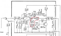
This is a very simple phono amp, but the components marked in the pic below look like the NFB circuits in power amps.
Is this indeed a NFB network?
If so, are there any differences in the way NFB would operate in a phono amp vs NFB in a power amp?
.
Is this indeed a NFB network?
If so, are there any differences in the way NFB would operate in a phono amp vs NFB in a power amp?
.
Attachments
Last edited:
It is feedback network. The 470k has a primary role in providing DC feedback to set the operating point of the circuit.
The parts above it and in parallel to it determine the frequency response (the RIAA curve).
If you had a power amp with that feedback network (all other things being equal) it would have the same response as your phono stage.
The parts above it and in parallel to it determine the frequency response (the RIAA curve).
If you had a power amp with that feedback network (all other things being equal) it would have the same response as your phono stage.
Thanks for pointing out the RIAA related components.
Back to the components marked in red, generally speaking would these be good candidates for component upgrading in most phono amps?
Some (Cordell et al) recommend using non-polarized for the larger value electrolytics (i.e. too large for film) in the shunt leg of NFB in power amps. Would the same thing apply for phono amps? Is there any reason that a Nichicon ES bipolar electrolytic should not be used for C105a?
And for the 470k ohm R108a, might this be a good place for a high quality metal film resistor with low temperature coefficient?
Tempco of the resistors is really immaterial here, even a change of a 0.1C will change the semiconductor characteristics far far more than any passive. Also remember the 470k is effectively shunted by the feedback network and so its noise contribution is not that of a 470k alone, it is much lower.
I tend to believe that good quality commercial parts usually fit the bill when it comes to caps but if you want to use a bi-polar then that is fine.
I tend to believe that good quality commercial parts usually fit the bill when it comes to caps but if you want to use a bi-polar then that is fine.
I partly disagree with Mooly, which is unusual but so be it:
If the feedback loop does what it is supposed to do, the response of the amplifier will be very sensitive to inaccuracies, non-linearities or other non-idealities of the feedback components and very insensitive to variations of the active parts. Therefore I would use accurate and linear components for C106a...C108a, R106a...R109a, which means components with a small tolerance and definitely no ceramic class II capacitors. C105a is less critical than the other components, as it only sets the subsonic roll-off together with R106a.
In particular, if that (M) behind the values of C106a, C107a and C108a is their tolerance code, then they have a tolerance of +/- 20 %, which is way too large for RIAA correction components. It would then definitely make sense to replace them with accurate capacitors, like +/-1 % or +/-2.5 %.Then again, maybe (M) is a reference to a note that we can't see in post #1. Do you know what the (M) stands for in this case?
Regarding C105a: bipolar electrolytic capacitors distort less than polar electrolytic capacitors, but the distortion of polar electrolytic capacitors is already negligible for most applications, especially when they work at low signal current levels like C105a. Then again, some types of bipolar electrolytic capacitor are quite cheap. So, do you want to spend a negligible amount of money on a negligible sound quality improvement?
@Marcel
"Regarding C105a: bipolar electrolytic capacitors distort less than polar electrolytic capacitors, but the distortion of polar electrolytic capacitors is already negligible for most applications, especially when they work at low signal current levels like C105a. Then again, some types of bipolar electrolytic capacitor are quite cheap. So, do you want to spend a negligible amount of money on a negligible sound quality improvement?"
I asked about that in a different topic, but i didn't offer enough data for acear cut answer , because the signal level must not reverse the bias through the capacitor:
https://www.diyaudio.com/forums/par...asured-120db-thd-140db-imd-2.html#post6282759
In a preampifier's case like this phono one , the capacitor in the feedback path should not be reversed biased which makes me think that actually a unipolar cap should provide lower distortion than a bipolar one there. Am I wrong?
Aluminium electrolytic capacitors (aluminum for the Americans) can handle 1.5 V ... 2 V in reverse before they start to conduct (and explode if the current gets too large). What I recall from Cyril Bateman's series of articles in Electronics World, see Cyril Bateman's Capacitor Sound articles | Linear Audio NL , is that even when the capacitor isn't driven in reverse at all, bipolar capacitors generally distort less than polar ones.
Just saw it...indeed...but his measuremments are with 300mv...1v signal while there we have a 1...10mv usual input.Would a unipolar electrolitic behave the same at 100 times lower signals ? A unipolar capacitor has higher losses but lower impedance than a bipolar.What would be a real outcome for that?Even when looking in very good audio equipment i saw they always use unipolar capacitors at low level if biased as usually the bias in a phono preamp is always lower than 2v...
Last edited:
I can't think of any reason why a bipolar capacitor's distortion would become larger than a unipolar capacitor's distortion at very low levels, but it would probably be very difficult to measure this, as both will have an astronomically low distortion at these levels.
Hopefully most phono amps already use metal film resistors and PP or PPS caps, so no need at all.Thanks for pointing out the RIAA related components.
Back to the components marked in red, generally speaking would these be good candidates for component upgrading in most phono amps?
.....
If the feedback loop does what it is supposed to do, the response of the amplifier will be very sensitive to inaccuracies, non-linearities or other non-idealities of the feedback components and very insensitive to variations of the active parts. Therefore I would use accurate and linear components ....
THIS ^^^
In particular, if that (M) behind the values of C106a, C107a and C108a is their tolerance code, then they have a tolerance of +/- 20 %, which is way too large for RIAA correction components. It would then definitely make sense to replace them with accurate capacitors, like +/-1 % or +/-2.5 %.Then again, maybe (M) is a reference to a note that we can't see in post #1. Do you know what the (M) stands for in this case?
There is no note on the schematic that refers to the "M" marking. Isn't M sometimes used to refer to polyester (i.e. Mylar) capacitors? All three of the caps with this designation in this sample are those green mylar types. The tolerance code on them is J.
Regarding C105a: bipolar electrolytic capacitors distort less than polar electrolytic capacitors, but the distortion of polar electrolytic capacitors is already negligible for most applications, especially when they work at low signal current levels like C105a.
.....
Would signal current levels be significantly lower in a typical phono amp vs signal current levels in a power amp? What would be typical values for signal current in a phono amp and a power amp?
.
Last edited:
How much signal current flows through the electrolytic capacitor is mainly determined by the input signal level and R106a. R106a is of the same order as you could expect in a power amplifier, but the input signal level is 1 to 2 decades lower than in a power amplifier that gets driven to its maximum power: tens of millivolts versus 1 V or so.
Tolerance code J stands for +/-5 % and Mylar is not the greatest capacitor dielectric, so replacing those capacitors with +/- 1 % or +/- 2.5 % polystyrene or polypropylene capacitors may give a subtle improvement of the sound quality. What type and tolerance of resistors are used for R106a...R109a?
Tolerance code J stands for +/-5 % and Mylar is not the greatest capacitor dielectric, so replacing those capacitors with +/- 1 % or +/- 2.5 % polystyrene or polypropylene capacitors may give a subtle improvement of the sound quality. What type and tolerance of resistors are used for R106a...R109a?
You could replace R106a...R109a with 1 % metal film for better RIAA conformity and better matching between left and right.
Carbon film is prehistoric to my mind! Worth considering replacing with metal film and PP or PPS caps (polystyrene are harder to source these days, PP or PPS or teflon (PTFE) are good dielectrics, with PP being a popular choice but the others handle high temperatures better (for instance PP caps cannot be surface mount, they'd melt)).
You may not hear the difference if you do upgrade, but sensitive measuring equipment probably can tell the difference!
You may not hear the difference if you do upgrade, but sensitive measuring equipment probably can tell the difference!
@Mooley good point about the RIAA components being in parallel with the larger feedback resistor
@MarceldvG Good and logical component upgrade suggestions, thank you. To be clear, my inquiries here are as much about my general knowledge, for future projects, as they are for possible component changes in this particular amp. I rebuild vintage integrateds (mostly), about one or two a year. This particular one is a lower-end (but very nice sounding) 35w Sherwood S-402CP. I like to be selective in component upgrading as opposed to some who, for example, might do a complete re-resistoring from CF to MF. I prefer to target areas that are more critical and yield a higher return, as I believe is the case for NFB components. Now I know where (and why) to focus my attention in phono amp circuits.
@Mark Tillotson I don't doubt that use of carbon film resistors en masse seems odd to many here in these forums, where DIY building using modern components is the norm. But I don't think that history has yet forgotten CF 🙂. In the 70's and early 80's gear that I have worked on, carbon film is by far the most common type of resistor, with MO being used for higher power and a few MF and CC tossed in here and there. Surprisingly, understanding the ways in which MF is superior to CF, the old amps chock full of CF resistors can sound pretty good.
Thank you all for the good information and excellent suggestions
Last edited:
A peculiarity of moving-magnet cartridges is that the response in the upper octave of the audio band is sensitive to the load, which in your circuit is mainly set by R102a, C102a and R103a. The inductance of the cartridge together with its losses, the cable and phono amplifier capacitance and the termination resistance form an LC low-pass filter that has to be tuned and damped to give the flattest overall response together with a mechanical resonance in the cartridge itself. It's a bit like a fourth-order Chebyshev low-pass filter with two orders in the mechanical and two in the electrical domain.
Unfortunately each cartridge model has a different optimal load capacitance, and the amount of capacitance that should be in the amplifier also depends on how capacitive the cable between the cartridge and the amplifier is. That's why you often see a switchable input capacitance on moving-magnet phono amplifiers. So another useful upgrade could be to figure out what capacitance is optimal in your case and to change C102a accordingly.
Unfortunately each cartridge model has a different optimal load capacitance, and the amount of capacitance that should be in the amplifier also depends on how capacitive the cable between the cartridge and the amplifier is. That's why you often see a switchable input capacitance on moving-magnet phono amplifiers. So another useful upgrade could be to figure out what capacitance is optimal in your case and to change C102a accordingly.
More helpful and insightful information, thank you. Apologies for misspelling your screen name above. I don't really have a "case" as I have no working turntable and don't foresee adding one any time soon, although this (or another) amp could also go to someone who does use a TT. If in the future this, or any other of my integrated amps, were chosen to be put into service with a turntable, I would then follow your suggestions including better caps and resistors in positions already mentioned.
So C102 solely determines input capacitance of this phono amp? No other components would need to change in order to adjust input capacitance? And changing C102 would have no detrimental effects elsewhere in the phono amp? In order to determine input capacitance as seen by the cartridge, would I connect the RCA input cable to the phono input of the amp, then measure capacitance at the other end of the cable?
And finally, how would I know what value to shoot for? Is this information included in the specs for every cartridge?
This is certainly getting deeper than I had anticipated 🙂 But I will use this information if/when a TT comes into the picture...
Last edited:
The collector-base capacitance of Tr101a will add a few pF of capacitance, as will internal wiring. Ideally, with infinite loop gain, the base-emitter capacitance of Tr101a and the capacitor in parallel with it will have no impact, but in reality the loop gain is finite, so they will also do something. All in all, I would guess you get 10 pF to 20 pF on top of C102a.
There are possible side effects: if you have to decrease C102a very much, it could affect the stability of the amplifier or the sensitivity to picked up RF signals.
The optimal load capacitance is normally in the cartridge datasheet. Do you have equipment to measure capacitances in the hundreds of picofarad range? I always measure it with an oscilloscope and a resistor.
Last edited:
- Home
- Source & Line
- Analogue Source
- Is this an NFB circuit in this phono amp?