hello
tell me something about this amp. please.
Can you see something to improve?
Can you see something very bad?
What's the RMS output
If someone can "dissecate" it to me this way;
Signal is entering 2 microfarads capacitor, and them amplified by Tr1 that makes.... etcetera.
Informs to you:
Is a professional cheap unit.... the lowered power from three "brothers", use to Public Adress with DC to DC converters supplies or small generators.... face is black, to mount in Standard 19 inches rack.
I never heard the sound, can i expect good performance?
schematic included, i will find picture and post it as soon i can
Not need to be kind or gentle... i do not like this protection too.
Factory model is Attack 1200
Carlos
Carlos
Attachments
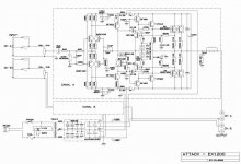
Well, I have a litttle extra time, so I'll make a few comments just to start the ball rolling.
From the power supply rail voltages, output power will probably be around 100 watts at 8 ohms.
Good choice of output transistors, though the omission of any base stopper for the outputs is slightly worrisome. Also, these are the Toshiba versions; I'd use more than two pairs for this supply output voltage. Perhaps the protection circuit takes this into accout with regards to reactive low impedance loads; I don't have time to analyze (your homework assignment? 😉
Emitter degneration resistors are rather large.
The drivers are a very odd choice; these are old, rather slow parts from TI; the most to recommend them being price. Why not MJE15031/33, apart from cost?
Unity gain at DC with big honkin electrolytic cap in feedback loop, and no clamp diodes; not an optimum choice in the 1970's, and certainly not now.
The VAS transistors are passively compensated to ground; if you're going to use feedback overall, why load down the VAS stage and pass up the opportunity to linearize it by implementing the VAS compensation in local feedback? I made the same mistake in the 70's; it's almost 30 years later; time to move on!
Next, it's kind of pointless to dump the differential output on the feedback leg into a resistor that isn't connected to anything else- might as well at least use the output current on the feedback side in some positive way, and go for a folded cascode connection into the emitter of the VAS amplifer transitors.
That's of course assuming you don't scrap the whole thing and start from scratch. 🙂
Last, if one is going to use a bipolar front end, let's be a little creative and "borrow" from Tektronix and use their cascode compensated feedforward circuit; requires using a cascode on the front end, and an extra set of differential tranistors, but MAN can you make the differential transfer function linear that way... and that's pretty important for the front end behavior of any amplifier. This stage is so often the one that is neglected...
I hope my silly meanderings haven't bored you. Is this a musical instrument or PA amplifier? It's easy to critique someone else's work, you know, but not always easy to do better while spending less money....
Best regards,
Jon
I really like very much your words
Very kind way, thank you sincerily.
I will save and read it again to understand completely.
I will have not a good knowledge, all the time assembling other people designs.
Now a day i am interest in improve my knowledge... and this is the correct place.
Pleace, can you explain in easy words, without some calculation or complicated names, like teach to a beginner, how exactly works this stop resistor.
In my idea, i will lose voltage.
Mr Pass and many other experienced as you are talk always about this stopper resistor.
Please, your help to put me out of the ignorance.
None of the words written here are ironic, sad, oposite related what i really think, nor a game or a joke nor a lye and nor a trap!
Carlos
Hello Carlos,
Sometimes, in a simple circuit with only one output transistor, a base stopper or gate stopper resistor is not necessary to prevent local oscillation of the power transistor or driver. But especially as you add devices in parallel, the assymetric (un matched lead length) of the layout makes possible a difference in response between the devices which can make the circuit look more like an oscillator circuit than an amplifier circuit at very high frequencies, especially with a capacitive load.
This stopper resistor may not be very large, and their are techniques to reduce it's size, but these I don't share. 😉 Sorry!
If you look at a lot of the circuits on the web of high power designs with multiple output transistors, they will usually show these extra resistors.
They are often necessary on the driver transistor also. This is a function of the driver transistor bandwidth, and again, the total circuit behavior with a reactive output load.
For example, it is my preference not to have an output inductor in the amplifier- this has a worsening affect on sonics, in my opinion. But without this inductor, even ignoring the behavior of conventional feedback loops, and their stability requirements, the output stage can oscillate by itself, with a capacitive load, due to the gain and bandwidth of the transistors. The trick is to be able to use the best, most linear, fastest transistors in a way which doesn't turn them into oscillators.
I do work for companies under contract from time to time, so while I can discuss general principles, there are specific circuit techniques I can't discuss. At best, I can only hint that solutions exist... 😉
Best regards,
Jon
Leach Amplifier
This is the original Leach amplifier published in Audio magazine. I think it was in 1977. There are a few mods and some parts are different. It was a great amplifier for 1977. I built dozens of them for mobile DJ systems and they are quite reliable. The S/N was very good and the sound quality is quite decent. While not today's state of the art, you could do a lot worse.
See my free schematics site at: www.schematicsforfree.mattsoft.net
Thank you JonMarsh and DmFraser
Wonderfull explanation Jon Marsh, hundred percent understood.
I am thinking about Standing Waves in audio circuits.
Also i am starting to think about ground planes. I gonna use all schematics a assemble the stop resistor.
Thank you, very kind, but the secrete made me think about in how to discover (smiling ashamed to be so silly).
DmFraser, also thank you, i already assemble the Leach amps... all them, all versions....but i could not perceive the increase of audio quality (subjective), and, as i like some harmonic distortion i am not able to make a qualified judgement related to this amplifier. I never try do discuss with someone as Mr Leach, because i know his importance, i read all he does and i know very well how he is qualified and also put in practice all produce.
I perceive, clearly, the spectacular amount of power the leach amplifier produce. In those times i had not a good speaker as reference, now i have, also nor a digital sinal input in a amplifier, nor a digital output in a CD Player, so, i will assemble it again, was dismounted to use parts again in other's amplifiers....but i will do it again.
Thank you to remember Mr. Leach, i will visit to see and record informs.
Carlos
Re: Thank you JonMarsh and DmFraser
If JonMarsh thinks there is a point in keeping it secret, you most
probably have no reason to feel silly for not figuring it out.
destroyer X said:
Thank you, very kind, but the secrete made me think about in how to discover (smiling ashamed to be so silly).
If JonMarsh thinks there is a point in keeping it secret, you most
probably have no reason to feel silly for not figuring it out.
This another one is a little bit better
Dificult to find schematics.
When i was young, all the electronics always had the schematics inside...now this awfull thing to try to turn home small repairs more difficult.
This other Atack model, model 3000 uses CCS and some stop resistors.
Here in Brazil factories and assembling lines are using adhesive with a crazy P.M.P.O Watts.... enormous numbers!. The call that Peak Music Power Output, but is something alike multiply by 30 the maximum power distorted and super excited, minumum allowed charge, adding both channels... Is this Universal lye?
Are this in use in your country too. An amplifier with 100 watts consumption and 4700 watts output!... impossible calculations
Carlos
Attachments

Re: This another one is a little bit better
Carlos,
I was able to get schematic diagrams for all commercially available electronic equipment in Brazil (Cygnus, Polyvox, Gradiente, Tojo) from Eltec Editora. I used to buy them at Litec in Sao Paulo. I don’t know where you live but you can find a retailer here: http://www.eltec.com.br/revendedores.htm
====================================
Eu consegui comprar todos os diagramas esquematicos de equipamentos disponiveis no mercado brasileiro (Cygnus, Polyvox, Gradiente, Tojo) publicados pela Eltec Editora. Eu costumava compra-los na Litec em Sao Paulo. Eu nao sei aonde voce mora, mas eles tem uma lista de revendedores aqui: http://www.eltec.com.br/revendedores.htm
destroyer X said:Dificult to find schematics.
Carlos,
I was able to get schematic diagrams for all commercially available electronic equipment in Brazil (Cygnus, Polyvox, Gradiente, Tojo) from Eltec Editora. I used to buy them at Litec in Sao Paulo. I don’t know where you live but you can find a retailer here: http://www.eltec.com.br/revendedores.htm
====================================
Eu consegui comprar todos os diagramas esquematicos de equipamentos disponiveis no mercado brasileiro (Cygnus, Polyvox, Gradiente, Tojo) publicados pela Eltec Editora. Eu costumava compra-los na Litec em Sao Paulo. Eu nao sei aonde voce mora, mas eles tem uma lista de revendedores aqui: http://www.eltec.com.br/revendedores.htm
Thank you Mr. Grimberg
Thank you, i will go there.
Carlos
"O Rio continua lindo, apesar das balas passarem de um lado pro outro...mas é bronca entre êles, de vez em quando algum inocente dança...mas ainda é lindo!"
Thank you, i will go there.
Carlos
"O Rio continua lindo, apesar das balas passarem de um lado pro outro...mas é bronca entre êles, de vez em quando algum inocente dança...mas ainda é lindo!"
Mr Milwood
Hello again for you Mr. Milwood.
In this new word of fast communications, is really dificult to imagine that all the things posted as threads are really a owner design, from the begining to the end only calculations.
There is no more originality.... the origin is a valve amp.... all those you see today are some kind of adaptation from industrial designs. People use simulators or schematic design programs and if you take a good look, you will see a Sony Thopology in first stage, A kenwood CCS idea in second stage, Mr leach idea in output.... so.... think about this one is mine or yours or trade mark is really something that belongs to someone more perfect than the real perfection.
If you want to protect also Brazilian Schematics, that is changed freely, you pay sometimes a quarter dollar for a xerox copy every street corner.... to put all the things correct again we must close the world's door.... disapear with all mankind and construct everything again.
If you put your E mail, as other do, i will tell you something good to protect.
Do you really think that designers do not use ideas one from each other?... do you really believe in that sittuation.... if they do that they will appear with a capacitive or transformer coupled amplifier... all the things done is a result of entire world efforts and communication, one good idea from here and other from there.
Best regards,
Carlos
- Status
- Not open for further replies.
- Home
- Amplifiers
- Solid State
- Is this amplifier good?