Hey all,
I have been playing with my Current Drive modified LM3886 based amp...so far for home Audio, well, didn't really perceive a "positive influence" on my Quad ESLs (sounds different, yes, but better?)
But for my homemade LM3886 based Guitar amp, I absolutely love it with my Roland JC120 JFET based DIY preamp.
Now I was just fixing a friends Fender Stage Lead and was looking at the schematic (attached)...I notice (in red circle) the neg/Grnd speaker lead is grounded with a .22ohm resistor and is actually part of the Feedback circuit... is this amp running in Current Drive?
Attachments
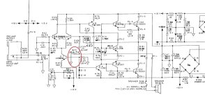
The signal that apears across the 0R22 is fed as negative feedback into the amplifier, through the low value capacitor that makes it ineffective at lower frequencies. There is a level of phase shift as well.
This has a compressing effect on the signal to the loudspeaker as the more peaks of power across the speech coil means the greater the current across the 0R22 so the greater the applied nfb creating a reduction in peak output at that power level.
The amplifier is a standard quasi complimentary class AB solid state amplifier. Nothing more.
OK, I saw the note: "Negative Speaker Termination is not Amplifier Ground" on Schematic and got me thinking...
Would a simple mod make it a Current Drive Amp?
Would a simple mod make it a Current Drive Amp?
What I'm seeing is that the quantity being fed back is the current through the speaker, making this a series-series feedback topology, meaning that the output is a current and the input is a voltage. The voltage across R71 (the 0.22 ohm resistor) is the speaker current times 0.22 (a close approximation).
output/input is current/voltage having units of amps/volts = 1/ohms implies that gain is a conductance.
The feedback factor is very nearly 1/0.22 = 4.54 amps/volt. Closed loop gain approaches 1/(feedback factor) or 0.22 amps/volt = 0.22 ohms.
Capacitor C44 appears to be big enough to pass all frequencies of interest, but it blocks DC. So there is no global DC feedback.
I don't have vast experience with audio power amplifiers, but from a classical network theory perspective it sure looks like a transconductance amp to me.
Tom
I see a combination of transconductance and voltage feedback: series feedback at the input, both series and shunt feedback at the output. That should result in an output impedance that is neither tending to zero nor to infinity with increasing loop gain, but tends to some finite value determined by the feedback network.
Edit: just wrote out the equations on an old envelope. Assuming that C44 is large enough and C43 small enough to be neglected, the output impedance at high loop gains is
R71*(R68+R69)/(R71+R69)
That's 4.96... ohm, so really neither current nor voltage drive.
Edit: just wrote out the equations on an old envelope. Assuming that C44 is large enough and C43 small enough to be neglected, the output impedance at high loop gains is
R71*(R68+R69)/(R71+R69)
That's 4.96... ohm, so really neither current nor voltage drive.
Last edited:

Yes, after reading your edit, I see there is some global feedback through R68 also. That probably helps stabilize DC output too. I had discounted that because the voltage at the inverting input is mostly due to the voltage across the 0.22 ohm resistor but I see the output voltage is not negligible.
It is current drive at audio frequencies. DC and ultrasonic feedback come directly from the output.
Ed
On what do you base that statement? It seems to me that both feedback paths are perfectly operational at audio frequencies.
It is "mixed mode". At high frequencies the voltage feedback is mostly filtered out and current feedback dominates, while in the bass there is more voltage feedback. The exact ratios depend on the resistor and cap values. It is a little bit similar to something I've been playing with lately.
Pay no attention to the messy parts and likely errors. It is a work in progress.

Pay no attention to the messy parts and likely errors. It is a work in progress.
The circuit in the opening post just has a 10 uF non-polar electrolytic DC blocking capacitor C44 that causes a corner frequency just below 20 Hz with R69 + R71, and a 6.8 pF phantom zero compensation (lead compensation) capacitor C43 that causes a corner frequency above 1 MHz with R68, nothing that looks like it is supposed to filter at audio frequencies.
But it's a first order filter slope, so, the influence only changes at a rate of 20dB per decade.
You could remove R68, short C44 and hope it remains stable and doesn't have too much offset. Or maybe change R68 into a T-network consisting of two resistors and a big capacitor to ground.
- Home
- Amplifiers
- Solid State
- Is this a Transconductance (Current Drive) amp?